Four Line LCD - LCD_EBIT


Closed Thread
Results 1 to 6 of 6
  1. #1
    Join Date
    Sep 2010
    Posts
    50

    Default Four Line LCD - LCD_EBIT

    Anybody got ideas on how to define/control two LCD_EBIT lines and still use the LCDOUT function? I have a Newhaven display that has an enable pin for the top half (first 2 lines) and also another one for the bottom half (last 2 lines). I tried to make a subroutine to redefine LCD_EBIT, but redefinition during runtime is not allowed. I can use LCDOUT to write to the top or the bottom half, but I need to write to both.... Any ideas would be appreciated.

  2. #2
    Join Date
    Mar 2008
    Location
    Gerogetown, Texas
    Posts
    94


    Did you find this post helpful? Yes | No

    Default Re: Four Line LCD - LCD_EBIT

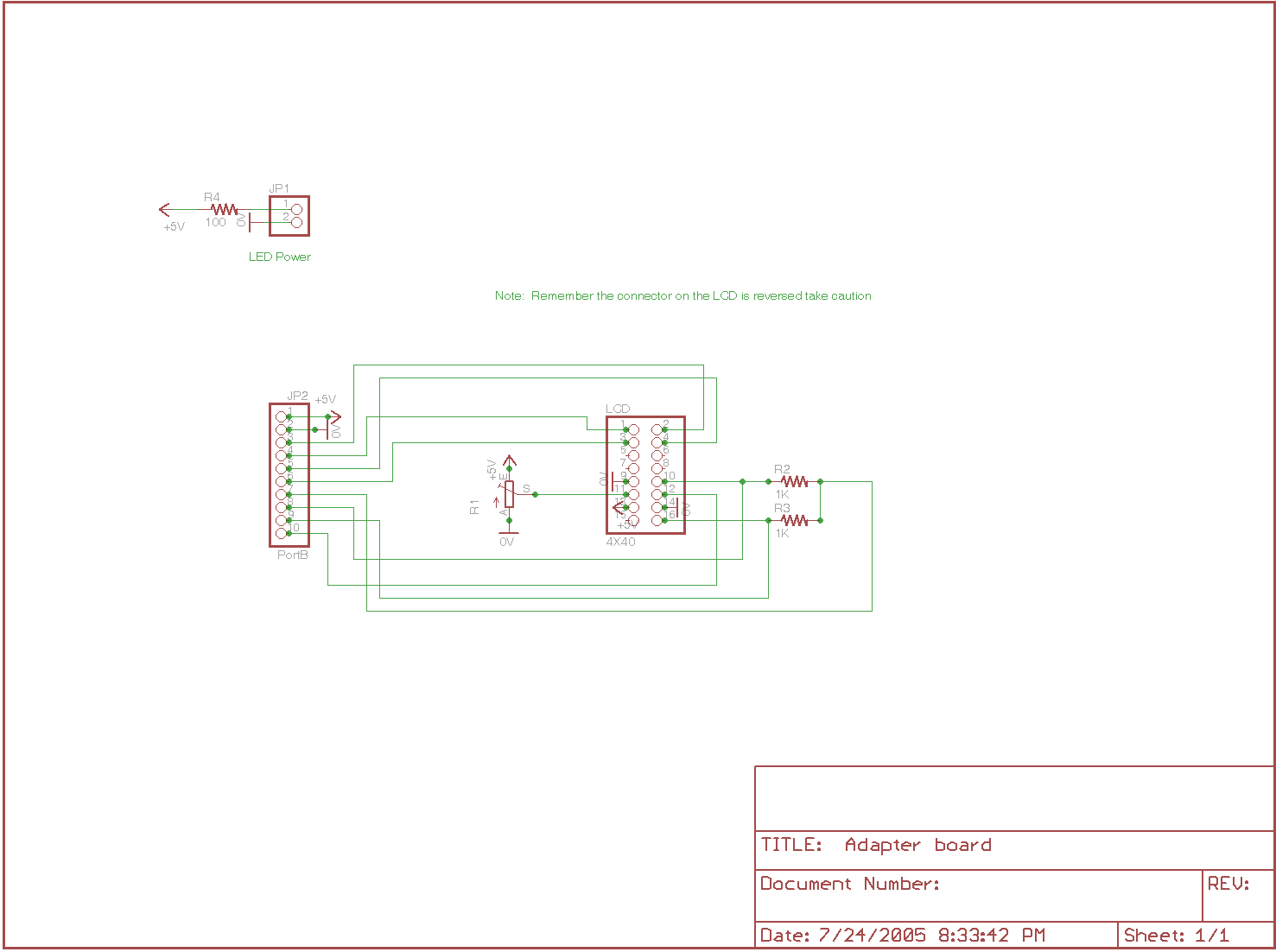
    Here is how I made a 4x40 work
    Name:  4x40  adapter.png
Views: 794
Size:  17.4 KB

    Code:
    '****************************************************************
    '*  Name    : USBladem4X40LCD                                    *
    '*  Author  : Dave Cutliff                                      *
    '*  Notice  : Copyright (c) 2005 Patent pending                 *
    '*          : All Rights Reserved                               *
    '*  Date    : 7/22/05                                           *
    '*  Version : 1.0                                               *
    '*  Notes   : PIC18F2455                                        *
    '*          :  LCD 4X40 Dual driver                                                 *
    '****************************************************************


    Define  OSC     48
    '**** LCD *******************************************************
    'Set LCD Data port
    DEFINE LCD_DREG PORTB
    'Set starting Data bit (0 or 4) if 4-bit bus
    DEFINE LCD_DBIT 4
    'Set LCD Register Select port
    DEFINE LCD_RSREG PORTB
    'Set LCD Register Select bit
    DEFINE LCD_RSBIT 0
    'Set LCD Enable port
    DEFINE LCD_EREG PORTB
    'Set LCD Enable bit
    DEFINE LCD_EBIT 3
    'LCD RW Register PORT
    'DEFINE LCD_RWREG PORTB
    'LCD read/write pin bit
    'DEFINE LCD_RWBIT 5
    'Set LCD bus size (4 or 8 bits)
    DEFINE LCD_BITS 4
    'Set number of lines on LCD
    DEFINE LCD_LINES 4
    'Set command delay time in us
    DEFINE LCD_COMMANDUS 2000
    'Set data delay time in us
    DEFINE LCD_DATAUS 50
    
    LCD1_Disable    var portb.2
    LCD2_Disable    var portb.1
    '*** Program variables *****************************************
    buffer1    Var    Byte[8]
    buffer2    Var    Byte[8]
    cnt    Var    Byte
    
    
    lcdcnt     var  byte
    'lcdchr     var  byte
    lcdlen     var  byte
    lcdline var byte
    lcd var byte
    lcdfunction var byte
    
    'x          var  byte
    'y          var  byte
    'j          var  byte
    k          var  byte
    'ln         var  byte
    'tmp1       var  byte
    '***************************************************************
        USBInit
    pause 500
    ' Initialize LCD
    input LCD1_Disable 
    input LCD2_Disable 
    LCDOut $fe,1   'clear lcd
    pause 100
    LCDOut $fe,2   'home
    LCDOut $fe,$0c 'Curser off
    LCDOut "              USB 4X40 LCD   "
    LCDOut $FE,$C0
    LCDOut "              DAVE CUTLIFF    "
    low LCD1_Disable 
    input LCD2_Disable 
    LCDOut $fe,1   'clear lcd
    LCDOut $fe,2   'home
    LCDOut $fe,$0c 'Curser off
    LCDOut "         Highspeed USB Project  "
    LCDOut $FE,$C0
    LCDOut "             August 2005    "   
    pause 100
    goto idleloop
    '*********************subrouteens*************************
     READ_SETUP:
      USBService
      lcdlen = buffer1[3]
      lcdline = buffer1[1]
      lcdfunction = buffer1[2]
      lcd = buffer1[0]
        if lcd= 0 then
            input LCD1_Disable 
            LOW LCD2_Disable 
              else
            LOW LCD1_Disable 
            input LCD2_Disable 
        endif  
      if lcdfunction = 1 then lcdout $FE,1
      lcdout $FE,lcdline
      
     RETURN
    
     Write_LCD:
          USBService
          lcdcnt = 1
          While lcdcnt < lcdlen
              for k = 1 to 7
              lcdcnt = lcdcnt + 1
              LCDOUT buffer2[k]
              if lcdcnt = lcdlen then goto outloop
              usbin 2, buffer2, cnt, idleloop
              next k   
         
          wend
     Return
    
    
     outloop:
        USBService                                ' Must service USB regularly
        USBOut 1, buffer1, cnt, outloop            ' Send the bytes back
     return
    '****************************************************************
    ' Wait for USB input of 8 numbers.
    idleloop:
        USBService                                    ' Must service USB regularly
        cnt = 8                                        ' Specify input buffer size
        USBIn 1, buffer1, cnt, idleloop
        gosub READ_SETUP
        gosub outloop
        usbin 2, buffer2, cnt, idleloop
        GOSUB Write_LCD
        gosub outloop
        
    
    goto idleloop
    Hope this helps

    Dave

  3. #3
    Join Date
    Jan 2006
    Location
    Istanbul
    Posts
    1,185


    Did you find this post helpful? Yes | No

    Default Re: Four Line LCD - LCD_EBIT

    You may want to use a 7408;
    This way, you can have one enable pin from PIC (coming from LCDOUT command), and two other Pins for each half.
    When you want to write to first half, HIGH first and LOW second; and the other way around for second half.
    Last edited by sayzer; - 16th July 2011 at 13:51.
    "If the Earth were a single state, Istanbul would be its capital." Napoleon Bonaparte

  4. #4
    Join Date
    Sep 2010
    Posts
    50


    Did you find this post helpful? Yes | No

    Default Re: Four Line LCD - LCD_EBIT

    Great Ideas. Thanks!

  5. #5
    Join Date
    Sep 2004
    Location
    montreal, canada
    Posts
    6,898


    Did you find this post helpful? Yes | No

    Default Re: Four Line LCD - LCD_EBIT

    It's really up to you to decide which one to use, 7408 or not. Cost effective wise, I think Dave's approach is the one. Back in time
    http://www.picbasic.co.uk/forum/showthread.php?t=626&
    Steve

    It's not a bug, it's a random feature.
    There's no problem, only learning opportunities.

  6. #6
    Join Date
    Sep 2010
    Posts
    50


    Did you find this post helpful? Yes | No

    Default Re: Four Line LCD - LCD_EBIT

    So far what I have ended up with was 2 transistors, NPN and PNP (3904 & 3906). I tied one line from the pic to control the transistors, two 2.2K resistor going from the control line to the base of each transistor. I connected the LCDOUT control line to the collector of the NPN and the emitter of the PNP. I use the control line to turn on or off the control line to pass the enable signal to either the enable1 or enable2 on the lcd. I only had to add one IO line from the PIC and 2 transistors. I have 4 of these displays on the panel so I was not excited about adding more chips to the design. Not sure how to upload a schematic, but would like everyone/anyone to see if they see a problem with the design. However, it works great!
    Thanks.

Members who have read this thread : 1

You do not have permission to view the list of names.

Posting Permissions

  • You may not post new threads
  • You may not post replies
  • You may not post attachments
  • You may not edit your posts