Help with pic16f690 -max232cpe


Closed Thread
Results 1 to 37 of 37
  1. #1
    Join Date
    Apr 2010
    Posts
    21

    Question Help with pic16f690 -max232cpe

    So i started to try out some serial com and after alot of struggling i have gotten it almoste to work.

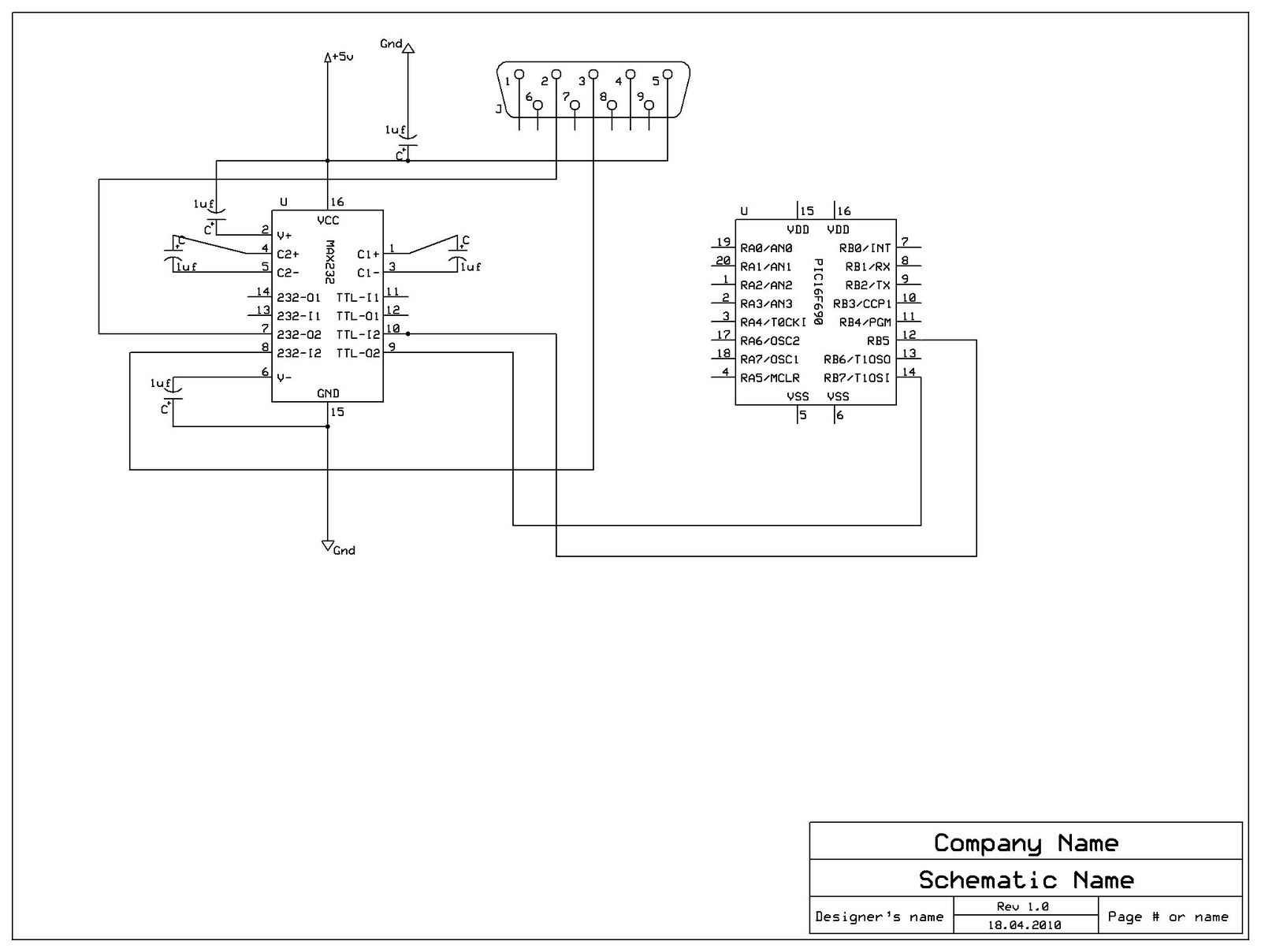
    i have pickit2 with pic16f690 and a demoboard with max232.

    max232:

    pin 1 & 3 - 1uf
    pin 4 & 5 - 1uf

    pin 2 - 1uf to vdd
    pin 15 - 1uf to gnd
    and gnd to vdd 1uf

    so i have been able to recive text on my computer from the pic but it's somehow malformed.

    i try to send "Hello World", 13, 10
    and i get
    Hello0World<(8A)>

    when i stop the pic i recive the space and cr and lf

    when i make the pic hserout the hserin i returns random alphas or signs.

    my current code is as follows:

    Code:

    DEFINE OSC 4

    'intcon=0 ' Interrupts disabled
    cm1con0=0 ' Comparator 1 disabled
    cm2con0=0 ' Comparator 2 disabled
    'cm2con1=0 ' Comparator 2 disabled

    ANSEL=0 ' Pins to be Digital
    ANSELH=0 ' Pins to be Digital

    Include "modedefs.bas"

    DEFINE HSER_RCSTA 90h
    DEFINE HSER_TXSTA 24h 'sets bergh = 1 or 20h sets = 0
    DEFINE HSER_BAUDCON 0h ' 0h
    DEFINE HSER_BAUD 9600 '16468
    DEFINE HSER_SPBRG 25
    'DEFINE HSER_CLROERR 1


    main:
    hserout ["Hello World", 13, 10]
    pause 1000
    goto main

    and i cant figure out why!

    im using picbasic with MC studio and MPASM

    Please HELP

  2. #2
    Join Date
    May 2008
    Location
    Italy
    Posts
    825


    Did you find this post helpful? Yes | No

    Default

    Code:
    DEFINE HSER_RCSTA 90h ' Enable serial port & continuous receive
    DEFINE HSER_TXSTA 24h ' Enable transmit, BRGH = 1
    DEFINE HSER_SPBRG 25  ' 9600 Baud @ 4MHz, 0,16%
    DEFINE HSER_CLROERR 1 ' Clear overflow automatically

    Tray to replace your USART setting with the one given above.

    Al.
    All progress began with an idea

  3. #3
    Join Date
    Apr 2010
    Posts
    21


    Did you find this post helpful? Yes | No

    Default

    Quote Originally Posted by aratti View Post
    Code:
    DEFINE HSER_RCSTA 90h ' Enable serial port & continuous receive
    DEFINE HSER_TXSTA 24h ' Enable transmit, BRGH = 1
    DEFINE HSER_SPBRG 25  ' 9600 Baud @ 4MHz, 0,16%
    DEFINE HSER_CLROERR 1 ' Clear overflow automatically

    Tray to replace your USART setting with the one given above.

    Al.
    Thx for replying, but i have tried that to. and still no go. when i change the usart settings to use 2400 bauds it wont work at all, then i just get alphas and numbers.

    can there be something wrong with my connections. iv tried with 2 max232 and same result. have i connected something wrong would this result in such an error.

    and one thing more, when i send a alpha, let's say "t" if i repeat that like 10 timer with 50ms pause i revice the correct letter back maybe once <- if i look a hserin and hserout

  4. #4
    Join Date
    May 2008
    Location
    Italy
    Posts
    825


    Did you find this post helpful? Yes | No

    Default

    What kind of terminal are you using?

    Can you post your wiring ?

    Al.
    All progress began with an idea

  5. #5
    Join Date
    Apr 2010
    Posts
    21


    Did you find this post helpful? Yes | No

    Default

    Quote Originally Posted by aratti View Post
    What kind of terminal are you using?

    Can you post your wiring ?

    Al.
    Well it looks like i found the probleme, i looked over the max232 data sheet and i frogot to connect vcc and gnd

    Now i recive the expected output but it wont read the input.

    Code:
    DEFINE OSC 4
    
    'intcon=0 ' Interrupts disabled
    cm1con0=0 ' Comparator 1 disabled
    cm2con0=0 ' Comparator 2 disabled
    'cm2con1=0 ' Comparator 2 disabled
    
    ANSEL=0 ' Pins to be Digital
    ANSELH=0 ' Pins to be Digital
    
    Include "modedefs.bas"
    
    DEFINE HSER_RCSTA	90h
    DEFINE HSER_TXSTA	24h 'sets bergh = 1 or 20h sets = 0
    'define HSER_BAUDCON 0h ' 0h
    'DEFINE HSER_BAUD	9600 '16468
    DEFINE HSER_SPBRG	25
    DEFINE HSER_CLROERR 1
    
    rxVal Var Byte
    HSEROUT ["Waitin signal"]
    main:
        hserin [rxVal]
        hserout [rxVal]
        'HSEROUT ["Test should work"]
        pause 20
    goto main
    Any ideas?

    And Thx for the help so far, sorry for not checking the schematics better
    and im using 232analyzer terminal software
    Last edited by krise86; - 18th April 2010 at 21:16.

  6. #6
    Join Date
    May 2008
    Location
    Italy
    Posts
    825


    Did you find this post helpful? Yes | No

    Default

    Can you post the schematic?

    Al.
    All progress began with an idea

  7. #7
    Join Date
    Apr 2010
    Posts
    21


    Did you find this post helpful? Yes | No

    Default

    Quote Originally Posted by aratti View Post
    Can you post the schematic?

    Al.

  8. #8
    Join Date
    May 2008
    Location
    Italy
    Posts
    825


    Did you find this post helpful? Yes | No

    Default

    Something doesn't work with your wiring:

    Max232 pin 10 should be connected to pic 16F690 pin 10 (RB7 Tx)

    Max232 pin 9 should be connected to pic 16F690 pin 12 (RB5 Rx)

    Connect a decoupling capacitor 10nF from Vdd to Vss on pic power pins.

    Al.
    All progress began with an idea

  9. #9
    Join Date
    Apr 2010
    Posts
    21


    Did you find this post helpful? Yes | No

    Default

    Well it is connected that way pin 10 -> rb7 and pin9 -> rb5

    The 16f690 was not in the schematics program but that how i connected it.

    but im reading -10v on rs232 pin 3 and 5 is that right?

    I dont have a 0,01uf can i use 0,1uf?
    wait i think it's on the demo board

  10. #10
    Join Date
    May 2008
    Location
    Italy
    Posts
    825


    Did you find this post helpful? Yes | No

    Default

    but im reading -10v on rs232 pin 3 and 5 is that right?
    Yes! Max232 is a voltage level translator.

    I dont have a 0,01uf can i use 0,1uf?
    Yes!

    Al.
    Last edited by aratti; - 18th April 2010 at 23:24.
    All progress began with an idea

  11. #11
    Join Date
    Apr 2010
    Posts
    21


    Did you find this post helpful? Yes | No

    Default

    Quote Originally Posted by aratti View Post
    Yes! Max232 is a voltage level translator.


    Yes!

    Al.
    That did nothing, is there a way to check if the signal is coming out from pin 9 on max232?

  12. #12
    Join Date
    May 2008
    Location
    Italy
    Posts
    825


    Did you find this post helpful? Yes | No

    Default

    That did nothing, is there a way to check if the signal is coming out from pin 9 on max232?
    Yes place a led with 1K in series from pin 9 to gnd.

    But, I am more interested on how many IO pins you are using. Now If you have inputs pins floating (not connected) this can produce wierd result.

    I noted in your code, that you are not setting the tris registers, please do it. Set all non used pins as output and place them to a logic zero.

    Example (I assume you are using only the serial pins) :

    TrisA = %00000000
    PortA = 0

    TrisB = %00100000 ' if the only input is pin 10 Rx
    PortB = 0

    TrisC = %00000000 ' if none of the portC pins are used
    PortC = 0

    The above code has to be written on top of your code. It will set all non used port as outputs @ logic zero, avoiding to leave inputs floating.

    If your arrangement is different modify the tris command to suite your need.

    Al.
    Last edited by aratti; - 18th April 2010 at 23:50.
    All progress began with an idea

  13. #13
    Join Date
    Apr 2010
    Posts
    21


    Did you find this post helpful? Yes | No

    Default

    Quote Originally Posted by aratti View Post
    Yes place a led with 1K in series from pin 9 to gnd.

    But, I am more interested on how many IO pins you are using. Now If you have inputs pins floating (not connected) this can produce wierd result.

    I noted in your code, that you are not setting the tris registers, please do it. Set all non used pins as output and place them to a logic zero.

    Example (I assume you are using only the serial pins) :

    TrisA = %00000000
    PortA = 0

    TrisB = %00100000 ' if the only input is pin 10 Rx
    PortB = 0

    TrisC = %00000000 ' if none of the portC pins are used
    PortC = 0

    The above code has to be written on top of your code. It will set all non used port as outputs @ logic zero, avoiding to leave inputs floating.

    If your arrangement is different modify the tris command to suite your need.

    Al.
    I did that now but still nothing usful, it seems that the data is coming out from the max but it wont register at all i do get something when i send like 200 times with 10ms

  14. #14
    Join Date
    Feb 2006
    Location
    Gilroy, CA
    Posts
    1,530


    Did you find this post helpful? Yes | No

    Default

    Is the ground (pin #5) of the serial connector really connected to +5 volts like the schematic?

  15. #15
    Join Date
    Apr 2010
    Posts
    21


    Did you find this post helpful? Yes | No

    Default

    Quote Originally Posted by scalerobotics View Post
    Is the ground (pin #5) of the serial connector really connected to +5 volts like the schematic?
    No just i did not lay to much work in the schematics. but no it's connected to ground

  16. #16
    Join Date
    Apr 2010
    Posts
    21


    Did you find this post helpful? Yes | No

    Default

    here is the updated right one.

    And i found a probleme wich seems od. when using any freq other than 4mhz the buad rating is all wrong.
    check out this forum discussion about it

    http://www.mikroe.com/forum/viewtopic.php?f=13&t=11114
    Attached Images Attached Images  

  17. #17
    Join Date
    Apr 2010
    Posts
    21


    Did you find this post helpful? Yes | No

    Default

    I found another forum thred about turning the MCLRE_OFF

    how do i do that?

  18. #18
    Join Date
    Feb 2006
    Location
    Gilroy, CA
    Posts
    1,530


    Did you find this post helpful? Yes | No

    Default

    Quote Originally Posted by krise86 View Post
    I found another forum thred about turning the MCLRE_OFF

    how do i do that?
    Check the configuration word register. Page 201 of the data sheet.

  19. #19
    Join Date
    Apr 2010
    Posts
    21


    Did you find this post helpful? Yes | No

    Default

    Quote Originally Posted by scalerobotics View Post
    Check the configuration word register. Page 201 of the data sheet.
    that okey, but how do i do it in picbasic?

  20. #20
    Join Date
    Feb 2006
    Location
    Gilroy, CA
    Posts
    1,530


    Did you find this post helpful? Yes | No

    Default

    You can put them in your program, or you can edit them in PBP files. Either way, you will have to go to your PBP files, and find the one specific to your chip. Look for the 16f690.inc file, and either edit, or comment out the line

    Code:
    ;        __config _INTRC_OSC_NOCLKOUT & _WDT_ON & _MCLRE_ON & _CP_OFF
            __config _HS_OSC & _WDT_ON & _MCLRE_OFF & _CP_OFF
    It is easiest to just to comment it out, then copy and paste it back into the same file with your changes. That way you will be able to go back to the default. Many people prefer to comment it out in this file, then put it into their PBP code. To to this, you would add a line at the top of your program, like this:

    Code:
    @        __CONFIG _INTRC_OSC_NOCLKOUT & _WDT_ON & _MCLRE_OFF & _CP_OFF
    See http://www.picbasic.co.uk/forum/showthread.php?t=543 for a more in depth look

  21. #21
    Join Date
    Apr 2010
    Posts
    21


    Did you find this post helpful? Yes | No

    Default

    Okey so still working on this. i have registred that the rb5 is reciving something, what i dont know.

    So i looked at the max232 sheet and it says there should be a +10v on port 2 and -10v on port 6 but im reading -2.3 and +6.5 could that be the reson?

  22. #22
    malc-c's Avatar
    malc-c Guest


    Did you find this post helpful? Yes | No

    Default

    Can you provide details of the computer you are hooking this up to. Some laptops don't have enough "umph" to provide the voltages required when using PIC programmers, so it might be the same with the project your are working on.

  23. #23
    Join Date
    Apr 2010
    Posts
    21


    Did you find this post helpful? Yes | No

    Default

    Quote Originally Posted by malc-c View Post
    Can you provide details of the computer you are hooking this up to. Some laptops don't have enough "umph" to provide the voltages required when using PIC programmers, so it might be the same with the project your are working on.
    it's an self built desktop. with asus p6d motherboard and it should do the trick. but i have an pci serial with power options for setting up to 4 pins to 5 or 12 v.

    but i see that the voltage from the pickit is 4.8 maybe i should connect an ext pw sup?

    it's irritating because this should be such a small case and iv been stuck at this since like friday.

    And to all Thx for all the help so far!

  24. #24
    Join Date
    Apr 2010
    Posts
    21


    Did you find this post helpful? Yes | No

    Default

    Now i have tried external pw and still no go. the pics sends fine, but wont recive. I have no other ideas left.

    other than if the voltage on pin 2 and 6 on the max is +6 and -2 but should be +10 nad -10. what am i doing wrong?

  25. #25
    Join Date
    Feb 2006
    Location
    Gilroy, CA
    Posts
    1,530


    Did you find this post helpful? Yes | No

    Default

    Can you post your entire code with the trisb and all ... plus whatever code you are using to determine it is not receiving.

    Thanks,

    Walter

  26. #26
    Join Date
    Apr 2010
    Posts
    21


    Did you find this post helpful? Yes | No

    Default

    Code:
    DEFINE OSC 4
    
    ANSEL = %00000000 ' Pins to be Digital
    ANSELH = %00000000 ' Pins to be Digital
    TrisA = %00000000
    PortA = 0
    TrisB = %00100000 ' if the only input is pin 10 Rx
    PortB = 0
    TrisC = %00000000 ' if none of the portC pins are used
    PortC = 1
    
    CM1CON0 =0
    CM2CON0 =0
    CM2CON1 =0
    
    adcon1=0
    
    Include "modedefs.bas"
    
    DEFINE HSER_RCSTA	90h
    DEFINE HSER_TXSTA	24h 'sets bergh = 1 or 20h sets = 0
    'define HSER_BAUDCON 1h ' 0h
    DEFINE HSER_BAUD	2400 '16468
    DEFINE HSER_SPBRG	103
    DEFINE HSER_CLROERR 1
    rxVal Var word
    
    start:
    Hserout ["Hello World", 13, 10] ' Send text followed by carriage return and linef
    main:
    Hserin 10000,start,[rxVal] ' Get a char from serial port
    Hserout ["Got value:", rxVal] ' Send char out serial port
    pause 30
    goto main
    That's the code.

  27. #27
    Join Date
    Nov 2003
    Location
    Wellton, U.S.A.
    Posts
    5,924


    Did you find this post helpful? Yes | No

    Default

    DEFINE HSER_RCSTA 90h ' Enable serial port & continuous receive
    DEFINE HSER_TXSTA 20h ' Enable transmit, BRGH = 0
    DEFINE HSER_SPBRG 25 ' 2400 Baud @ 0.17%
    DEFINE HSER_CLROERR 1 ' Clear overflow automatically

    The above should be for 4MHz.
    Can you also post your configs and what are you using for an OSC?
    Dave
    Always wear safety glasses while programming.

  28. #28
    Join Date
    Apr 2010
    Posts
    21


    Did you find this post helpful? Yes | No

    Default

    I have already tried that, so it's still a no go.

    But no one has commented on the voltage levels of the max. it should say 10 but i dont get it higher than 7. when i rebuild the whole shematics on the breadboard the voltage got i little better but still no higher than 7

  29. #29
    Join Date
    May 2008
    Location
    Italy
    Posts
    825


    Did you find this post helpful? Yes | No

    Default

    But no one has commented on the voltage levels of the max. it should say 10 but i dont get it higher than 7. when i rebuild the whole shematics on the breadboard the voltage got i little better but still no higher than 7
    Check the capacitors used. See snap attached for value.

    Al.
    Attached Images Attached Images  
    All progress began with an idea

  30. #30
    Join Date
    Mar 2003
    Location
    Commerce Michigan USA
    Posts
    1,166


    Did you find this post helpful? Yes | No

    Default

    krise86, Depending on the capacitator values used with a MAX-232 the charge pump voltages should be around +-6 volts to +- 9 volts. The TRUE RS-232 spec calls out for mark,space voltages of +- 3 volts minimum... Some laptop computers now days do not meet the TRUE RS-232 spec limits as some only put 0 to +5 volts... That is why some laptop computers don't have a solid serial communications...

    Dave Purola,
    N8NTA

  31. #31
    Join Date
    Apr 2010
    Posts
    21


    Did you find this post helpful? Yes | No

    Default

    Yeah i am using 1uf caps, so it's not that. and i am reciving at this moment v- = -1.86 and v+ = 6.96.

    I found out that i can use the pickit 2 as logic analyzer. and i see the bytes roll inn when the pic send out to pc but not ther other way around.

    Im stumped... this sould work!
    I have followd all the guidelines and shematics and caps. i have also oredered some new max and pic's. also alot of caps and resistors. I really want this to work.

    Thx for all the help so far. i will get this to work! i hope

  32. #32
    Join Date
    Apr 2010
    Posts
    21


    Did you find this post helpful? Yes | No

    Thumbs up Got it working but not proud

    Okey so finally i got this working, but the story about how i did it is kinda BAD.

    So after a while i was beginning to wonder why it was reading wrong voltages. and i knew the connections where right, until i look really close to the serial cabel, i used a rs232 to rj45 and a cat5 cabel, but i somehow got the colors mixed up. So ground was not connected. heh.... well u think stupid you, and yes stupid me. not going to that mistake again. So then i started to check the connection on my breadboard and pow it splits in the middel where i had put my pic. so basicly i had half of the earth connections not connected. And i connected it this way after it was connected the right way. but then i did not have the pin 5 from rs232.

    Maybe it's a lesson to learn from all of this. ALWAYS check ur cabel and make sure pin5 is connected.

    BTW how many times have i answerd What colour is a ripe tomato?
    lost count

    Sorry to have wasted everybodies time but i really appricihate it.

    And i did learn alot from searching and reading around the net.

    Thx for all the help once again and sorry that im such an idiot

  33. #33
    Join Date
    Nov 2003
    Location
    Wellton, U.S.A.
    Posts
    5,924


    Did you find this post helpful? Yes | No

    Default


    Glad you got it working.
    Do not be sorry for making a mistake, it happens to all of us.
    I spent a just spent a couple days in something and the problem was not turning the ADC off!!! How many times have I told others to check that? More times than a tomato is ripe!!!
    Dave
    Always wear safety glasses while programming.

  34. #34
    Join Date
    Apr 2010
    Posts
    21


    Did you find this post helpful? Yes | No

    Default

    yeah but still.
    One more question tough. why cant i run a for loop?

    for count = 1 to 40
    pulsout PORTC.1,200
    pause 20
    next count

  35. #35
    Join Date
    Nov 2003
    Location
    Wellton, U.S.A.
    Posts
    5,924


    Did you find this post helpful? Yes | No

    Default

    COUNT is a reserved word, a command actually.
    Change it to CNT ot something and it should work.
    Code:
    for CNT = 1 to 40
    pulsout PORTC.1,200
    pause 20
    next CNT
    Dave
    Always wear safety glasses while programming.

  36. #36
    Join Date
    Apr 2010
    Posts
    21


    Did you find this post helpful? Yes | No

    Default

    i ended up with a while loop, but il try the for loop.

    Thx for the help. Il be coming back, waiting for a gps module it should be here in a couple of days
    Code:
        i = 1
        while i<40
            pulsout PORTC.1,pos
            i=i+1
            pause 20
        wend
    the for loop gave me and syntax error

  37. #37
    Join Date
    Nov 2003
    Location
    Wellton, U.S.A.
    Posts
    5,924


    Did you find this post helpful? Yes | No

    Default

    Quote Originally Posted by krise86 View Post

    the for loop gave me and syntax error
    Did you try CNT? Did you declare CNT as a variable?
    Dave
    Always wear safety glasses while programming.

Members who have read this thread : 1

You do not have permission to view the list of names.

Tags for this Thread

Posting Permissions

  • You may not post new threads
  • You may not post replies
  • You may not post attachments
  • You may not edit your posts