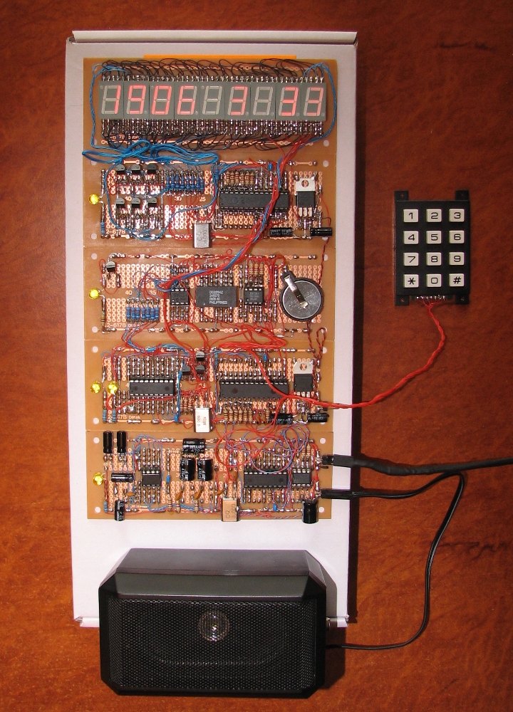
Amplifier Interference Issue


Closed Thread
Results 1 to 21 of 21
  1. #1
    Join Date
    Aug 2003
    Posts
    985

    Default Amplifier Interference Issue

    Hi Guys,
    I have a few projects where pics make sounds (as do a lot of us I imagine).
    In a few projects I have used a small 1 Watt amplifier to drive a loudspeaker.

    All is good, but I hear a little hum from the amp when it's supposed to be silent.
    If the project has a flashing LED or the like, I then Hear a hum flashing at two different frequencies.
    I assume this is interference from the pic itself.

    A solution I'm thinking of is to leave the amplifier on all the time,
    but to allow the pic to switch on the speaker only while a sound is being played.
    The interference is inaudible while a sound is actually playing.

    My question is.. What is a suitable circuit to achieve this?
    The amplifier chip is a TDA2822M.
    Cheers, Art.

  2. #2
    Join Date
    Jan 2009
    Location
    California, USA
    Posts
    323


    Did you find this post helpful? Yes | No

    Default

    Is the noise coming form the output pin of the PIC and fed to the input of your amp, or is it being coupled in through the power supply?

    If you disconnect and ground the inputs of your amps does it go away?

    If you set the PIC pin that drives it to an input (during the time you're not using it) would that help?

    steve

  3. #3


    Did you find this post helpful? Yes | No

    Default

    You've got a whole list of things to run down...

    Where is your power coming from? A battery, wall-wart, PC? If it's anything other than a battery you need to see how quiet the supply is. Wall-warts are incredibly noisy and unless you take care you are going to get noise. What kind of decoupling do you have on the supply? You're going to need something fat and something skinny. Start with 100uF-470uF electrolytic on the rail. Pair that with a 0.01-0.1uF ceramic (maybe both). Skipping this and you might as well forget it. You can go further and use a series resistor in the supply but start with the caps.

    How is the input connected? AC-couple (use a cap on the input to the amp). Something like a 0.47uF should do it. Then it doesn't matter if the PIC is an output or an input (the cap blocks DC. Regardless if it's an output high or low nothing is showing up at the amp. The only time the amp sees signal is when you are outputing "sound" as an AC waveform). Use a high value resistor to ground on the input of the amp (on the amp side of the cap). Something like a 1M ohm (the data sheet shows a 10K but this is to match the output from a preceeding pre-amp or line level. You don't need that coming from a PIC). This keeps the input at ground unless there is a signal.

    Are your grounds tied together at one point (preferably at the supply)? If you have multiple ground paths then you're going to get into trouble. Tie the supply leads together at the supply. Use a single wire from the output of the PIC to the input cap.

    Looking at the data sheet you should run this in BTL (bridge-tied load) configuration. This uses both amps in the package and gets rid of the big caps on the output (the 470's). This part uses a lot of caps, make sure you are using them. Keep the leads short and if you are using a "plug-strip" protoboard get rid of it and solder the stuff together. Flying leads between components are far better than proto-boards.

    There are amps out there that have an enable pin. You can get one of those and turn the amp on and off as you need. If something is battery powered this saves on power. This only masks the problem however; the hum and noise are still present unless you get rid of it.

    Mike Tripoli

  4. #4
    Join Date
    Aug 2003
    Posts
    985


    Did you find this post helpful? Yes | No

    Default

    Ok, that gives me a lot to think about.
    Unfortunately the protoboard has to stay (this is a one off).
    I am using a plugpack, but the interference sound seems vary according to what the pic/s are doing, so I don't know what that means.
    I don't think i've ever tested this particular project with a battery though,
    so that might be interesting, thanks

    I guess I'll revive this if I run into trouble.

  5. #5
    Join Date
    Aug 2006
    Location
    Look, behind you.
    Posts
    2,818


    Did you find this post helpful? Yes | No

    Default

    Quote Originally Posted by Art View Post
    . . .but the interference sound seems vary according to what the pic/s are doing, so I don't know what that means.
    That could be a variation in leakage across the diode's junction due to changes in load . . . Used to see that a lot in car alternators.
    If you do not believe in MAGIC, Consider how currency has value simply by printing it, and is then traded for real assets.
    .
    Gold is the money of kings, silver is the money of gentlemen, barter is the money of peasants - but debt is the money of slaves
    .
    There simply is no "Happy Spam" If you do it you will disappear from this forum.

  6. #6
    Join Date
    Aug 2003
    Posts
    985


    Did you find this post helpful? Yes | No

    Default

    Is that a rectifier diode in the plugpack power supply ?

    Hey mtripoli,
    How would you like to make a PCB for this:


    Give me a bit and I'll whip up a schematic with the transistors the wrong way round
    Nah just kidding

    I'm not actually using the 7805s at the moment because I have a 2 amp 5 Volt regulated wall supply.
    The plugpack is a charger for a Sony PSP, and I would have thought the caps would be in that.

    So it's a talking clock with a display now, but I also want to add an FM radio that I'm making with a Philips FM radio IC tonight.

    There should be some circuit to switch the input of the amplifier chip
    between the pic and the radio chip.
    Should I use signal transistors?
    Last edited by Art; - 3rd March 2010 at 09:38.

  7. #7


    Did you find this post helpful? Yes | No

    Default

    I don't know what the output of PSP supply looks like. I have never seen what a "plug-pack" (what we derisively call a wall-wart) looks like for the PSP. I would be very surprised if it has any kind of filtering at all. Usually these things are a transformer, a bridge (if you're lucky) and MAYBE a single cap (it could be a universal input switching supply as well. If so the thing most likely has tons of high frequency component on the DC. Some ceramic caps strategically placed may be all you need. LM78xx devices don't respond at these higher frequencies and will let a lot of this through). The manufacturer places the caps and related circuitry in the device being powered (for lots of reasons). So first, whenever you are using a "plugpack" put some big caps on the input of the supply to the board. 470uF-1000uF is not unusual. Use some ceramics as well. Watch the voltage; don't use a 6.3V cap on a "5V" supply (higher voltage never hurts). Typically voltage rating is under load, so a "5V" supply may actually be much higher than that.

    Mike Tripoli

  8. #8
    Join Date
    Jan 2009
    Location
    California, USA
    Posts
    323


    Did you find this post helpful? Yes | No

    Default

    hmmm.... using a wall wart for power.....

    Many "modern" wall warts now contain switching supplies instead of the traditional xformer/rectifier setup in order to meet minimum efficiency standards
    that now apply in many areas.
    That may well be the source of your noise. Like Mike said... an electrolytic cap of a few hundred uF, with 1 or more small (.01-.1uF) ceramic caps in parallel may help a lot.


    steve

  9. #9
    Join Date
    Aug 2003
    Posts
    985


    Did you find this post helpful? Yes | No

    Default

    Thanks Guys,
    a 1000uF cap across the supply almost eliminates the noise
    That's a bit big, but I'm sure I'll find a combination that works well.

  10. #10


    Did you find this post helpful? Yes | No

    Default

    Quote Originally Posted by Art View Post
    That's a bit big, but I'm sure I'll find a combination that works well.
    No it's not... 3x220uF is better, 2x470uF is ok... but 1000uF is not big...

  11. #11
    Join Date
    Aug 2003
    Posts
    985


    Did you find this post helpful? Yes | No

    Default

    I just mean a bit big looking on the circuit,
    and it might prevent PCB stacking with tight spacing (if I go that way).
    I'd rather use a couple of smaller ones.

    This one is to end up a talking clock radio.
    At last, a project I actually use in day to day life

  12. #12
    Join Date
    Nov 2003
    Location
    Greece
    Posts
    3,803


    Did you find this post helpful? Yes | No

    Default

    It is a big circuit and I can understand how difficult might be to change the connections.

    But in most cases that involve audio amps or pre-amps, the problem arises from the ground loops. And I see a lot on your photo Art.

    So, I would suggest to take cables from all the minus (ground points) of the circuit parts and connect them to a single point where your (-) of the power supply is.

    This wll also help you reduce the spikes on your digital power rail.

    I suppose that you are having different power line for the analog and digital parts, right?

    Ioannis

  13. #13
    Join Date
    Jan 2006
    Location
    Istanbul
    Posts
    1,185


    Did you find this post helpful? Yes | No

    Default

    Quote Originally Posted by Ioannis View Post
    ..
    So, I would suggest to take cables from all the minus (ground points) of the circuit parts and connect them to a single point where your (-) of the power supply is....

    Ioannis
    And, from right there, have a bobbin serially connected to GND, thus, all of your circuit will go to GND via that bobbin.

    The value of the bobbin is best found by experimenting.


    -------------------------------------
    "If the Earth were a single state, Istanbul would be its capital." Napoleon Bonaparte

  14. #14
    Join Date
    Aug 2003
    Posts
    985


    Did you find this post helpful? Yes | No

    Default

    there are 5 PCBs in the project picture, they are just close together.
    Each has a gnd and + 5 Volt rail, except the amp which takes power from
    whatever power is input before the 7805s, or from + 5 Volts in the case
    that I can supply the circuit with regulated 5 Volts like on a desk at home.

    All of those ground rails are connected together.
    It would have been exactly the same rail if the tracks ran vertical up one big board.
    Is there any difference?

  15. #15
    Join Date
    Nov 2003
    Location
    Greece
    Posts
    3,803


    Did you find this post helpful? Yes | No

    Default

    When you say "together" do you mean in a spagetti form one after another or in a star form?

    The enter of the star is where the power supply (-) should be connected.

    All other connections and configurations are creating ground loop currents.

    Also if possible use this kind of connection fr the (+) of the other pcb's too. The star topology is very important to minimize interferance. Thena good decoupling locally is also very helpful.

    Ioannis

  16. #16
    Join Date
    Jan 2006
    Location
    Istanbul
    Posts
    1,185


    Did you find this post helpful? Yes | No

    Default

    Attached Images Attached Images  
    "If the Earth were a single state, Istanbul would be its capital." Napoleon Bonaparte

  17. #17
    Join Date
    May 2004
    Location
    NW France
    Posts
    3,614


    Did you find this post helpful? Yes | No

    Default

    Hi, Art

    Nice piece of wrapping ... impressing !!!

    Seriously, I do not see the unforgettable ceramic capacitor ( 0.1 - 0.22µ multilayer ) which ever should be placed CLOSEST as possible to the Pic supply pins ... ( lower and upper right )

    Also, you should try to place the Xtal and its caps on the other side of the pic, close to the pic pins ... ( nice 8 Mhz emitter !!! ... lower right )

    there's lots of noise to catch here ...

    a big reservoir cap ( L.S.R. ) is also a must to place close to the multiplexed LED displays:
    they generate lots of noise ...

    Alain
    ************************************************** ***********************
    Why insist on using 32 Bits when you're not even able to deal with the first 8 ones ??? ehhhhhh ...
    ************************************************** ***********************
    IF there is the word "Problem" in your question ...
    certainly the answer is " RTFM " or " RTFDataSheet " !!!
    *****************************************

  18. #18
    Join Date
    Aug 2003
    Posts
    985


    Did you find this post helpful? Yes | No

    Default

    Thanks

    The 0.1 uF caps are there right next to every pic. They are blue.

    Quote Originally Posted by Acetronics View Post
    Hi, Art

    Nice piece of wrapping ... impressing !!!

    Seriously, I do not see the unforgettable ceramic capacitor ( 0.1 - 0.22µ multilayer ) which ever should be placed CLOSEST as possible to the Pic supply pins ... ( lower and upper right )

    Also, you should try to place the Xtal and its caps on the other side of the pic, close to the pic pins ... ( nice 8 Mhz emitter !!! ... lower right )

    there's lots of noise to catch here ...

    a big reservoir cap ( L.S.R. ) is also a must to place close to the multiplexed LED displays:
    they generate lots of noise ...

    Alain

  19. #19
    Join Date
    Aug 2003
    Posts
    985


    Did you find this post helpful? Yes | No

    Default

    Bah! bit of a nightmare project.

    I think the noise stopped when I was using a capacitor is because I was holding
    it with my fingers.

    I have tried a transistor OR gate to ground the input pin of the amplifier.
    The amplifier is connected to an FM radio circuit, and a pic pin that produces sound.
    The OR gate can receive a busy signal from either the pic or radio circuits
    to make it stop shorting the amplifier input to ground.

  20. #20
    Join Date
    May 2004
    Location
    NW France
    Posts
    3,614


    Did you find this post helpful? Yes | No

    Red face

    Quote Originally Posted by Art View Post
    Thanks

    The 0.1 uF caps are there right next to every pic. They are blue.

    Hi,

    Blue or not ...

    They still are TOO FAR from the pic supply pins ...

    Alain
    ************************************************** ***********************
    Why insist on using 32 Bits when you're not even able to deal with the first 8 ones ??? ehhhhhh ...
    ************************************************** ***********************
    IF there is the word "Problem" in your question ...
    certainly the answer is " RTFM " or " RTFDataSheet " !!!
    *****************************************

  21. #21
    Join Date
    Aug 2003
    Posts
    985


    Did you find this post helpful? Yes | No

    Default

    Quote Originally Posted by Acetronics View Post
    Hi,

    Blue or not ...

    They still are TOO FAR from the pic supply pins ...

    Alain
    You think I'd hear less noise from the amp if I moved the 0.1uF caps closer to each chip?

    I had another idea. What if next time I used a copper clad board of the same
    size underneath the proto PCB, so I could drill one layer down to a ground plane at any location?

Similar Threads

  1. Controlling volume of an amplifier..
    By joseph Degorio in forum Schematics
    Replies: 33
    Last Post: - 17th May 2014, 04:15
  2. Puzzling issue with I2CWRITE to 24LC512
    By aberco in forum General
    Replies: 4
    Last Post: - 22nd August 2008, 17:47
  3. Pic Interference and Power Filter Question
    By Hylan in forum General
    Replies: 3
    Last Post: - 24th January 2008, 07:50
  4. 18F1320 ... Strange Memory
    By Acetronics2 in forum mel PIC BASIC Pro
    Replies: 43
    Last Post: - 9th April 2006, 09:55
  5. Inductive Load Switching and Interference
    By hughgoodbody in forum Off Topic
    Replies: 0
    Last Post: - 23rd December 2005, 17:59

Members who have read this thread : 1

You do not have permission to view the list of names.

Posting Permissions

  • You may not post new threads
  • You may not post replies
  • You may not post attachments
  • You may not edit your posts