To Generate Sine Wave Using PCPWM of PIC18F4331 (Issue)


Closed Thread
Results 1 to 7 of 7
  1. #1
    Join Date
    Jan 2010
    Posts
    10

    Default To Generate Sine Wave Using PCPWM of PIC18F4331 (Issue)

    Hi everyone,
    I am trying to generate one sine wave using PCPWM of PIC18F4331. I have set the frequency of PWM to 20KHz (PTPER 249) and I am using 20MHz crystal. I have calculated the resolution which is equal to 10 bits. Hence, a value of 0 is equal to 0% duty cycle and a value of 1023 is equal to 100%.

    I generated a sine table of 19 values from 0 to 90 degrees in steps of 5 with a scaling factor of 128. I have set TMR0 to 8 bits and it always starts counting from 200 to 255 then overflows. Once it overflows, it updates the pointer to the table. I believe that to complete 1 cycle, 36 samples of the sine wave are required. The TMR0 interrupt is generated every 55*1.6 us (instruction cycle) which is equal to 88 us. Hence, one cycle is generated every 36*88 us = 3.2 ms (315 Hz).

    The sine table I used is below
    //0-90 sine wave 128 scaling in step of 5
    const char sineTable[19]={0x80,0x8B,0x96,0xA1,0xAC,0xB6,0xC0,0xC9,0xD2,0xD B,0xE2,0xE9,0xEF,0xF4,0xF8,0xFC,0xFE,0xFF,0xFF };

    One more thing, the sine value once it is selected it gets multiplied by 200 then limited and sent to PDC0H and PDC0L to increase the ON time of the signal. The way I did is the max value in sine table is 255*200 = 51000 then I shift this value to the right 6 times (10bits) then send it PDC0. I am not sure if what I did is right or wrong.

    I am using ISIS to simulate my program. at the moment, My sine signal is at 20 Hz and the amplitude is 1.5V P-P. What I am doing wrong? How can I increase the amplitude of the sine wave? Also can I improve the sine wave shape?

  2. #2
    Join Date
    Dec 2009
    Location
    Kalamazoo
    Posts
    42


    Did you find this post helpful? Yes | No

    Default

    hi,
    i've been thinking about this kind of project, and im leaning towards microchips AN655 app note. it uses a 32 step lookup table to produce a 60hz sine wave, 5 bit resolution, at 19.2 khz pwm. it also gives you some code (in assembly), and ive been trying to decode that, from the comments, and the assembly code, to pbc pro, where i can easily manipulate it.
    theres a big thread about a sine wave inverter, but apparently, its "top secret" and the guys are bound by corporate laws from disclosing the designs and code. the lookup table in the code is really helpful because you dont have to calculate the lookup values. good luck on your project.
    Last edited by ScaleRobotics; - 2nd July 2010 at 10:24. Reason: app note correction
    NAG CON WIFE!
    WIFE VAR MOOD

  3. #3
    Join Date
    Aug 2005
    Location
    Michigan, USA
    Posts
    224


    Did you find this post helpful? Yes | No

    Default

    Quote Originally Posted by Cyborg View Post
    Hi everyone,
    I am trying to generate one sine wave using PCPWM of PIC18F4331
    What is the frequency of the sine wave you're trying to generate?

  4. #4
    Join Date
    Jan 2010
    Posts
    10


    Did you find this post helpful? Yes | No

    Default

    There is no frequency in mind. I just want to learn more about TMR0 interrupt and the generation of sine wave using PWM technique. The only thing I didnt mention in my first post is that once TMR0 interrupt is occurred, in the interrupt function, the TMR0L value is set to 200. So it counts up to 255 and then overflows.
    Last edited by Cyborg; - 15th February 2010 at 19:40.

  5. #5
    Join Date
    Feb 2006
    Location
    Gilroy, CA
    Posts
    1,530


    Did you find this post helpful? Yes | No

    Default Sine wave using DT interrupts

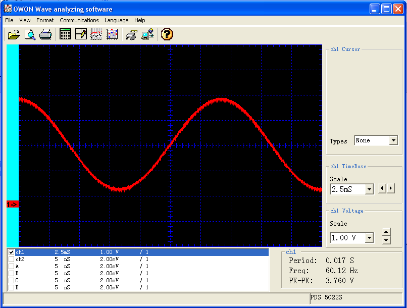
    I've been interested in this as well. Using the principles of AN655, (only using DT_INTS and HPWM, rather than software PWM), here is some code. Not sure how clean my sine wave is, but it doesn't look too bad on the scope. Might be better if I trim the leads on the breadboard filter. Hopefully someone can have some fun with it. I have a feeling it might be smoother in DT_INTS using an ASM interrupt routine, so that is where I am headed next, thanks to Darrel and Bruce. Will try to give that a shot.


    Code:
    ;    Circuit Diagram: 
    ;    PIC18F2431
    ;   Filter Diagram
    ;        
    ;               2.7k            2.7k    
    ;    RC2  ___/\  /\  /\______/\  /\  /\________ Analog Output
    ;              \/  \/    |     \/  \/     |  
    ;                        |                |
    ;                      ----- 0.1uF      ----- 0.1uF
    ;                      -----            -----
    ;                        |                |
    ;                       GND              GND
    ;
    ;
     
    define OSC 40
    asm
        __CONFIG    _CONFIG1H, _OSC_HSPLL_1H
        __CONFIG    _CONFIG2H, _WDTEN_OFF_2H & _WDPS_512_2H
        __CONFIG    _CONFIG4L, _LVP_OFF_4L
    endasm
     
    ADCON0 = 000000
    ADCON1 = 000000
    trisb = 111111
    trisc = 111011
    trisa = 111111
    TMR2 = 16
    PR2 = 129       ;set for 19.2Khz HPWM
    LED1 var portC.1          
    LED2 var portC.3          
    Duty var word
    CCP1CON.3 = 1        ' set to pwm mode
    CCP1CON.2 = 1
    T2CON.2=1
    T2CON.0=1
    STEPCOUNT var byte
    stepcount = 32
    ; Set sine "table" in an array
    sineval var byte[33]
    sineval[1] = 128
    sineval[2] = 148
    sineval[3] = 167
    sineval[4] = 185
    sineval[5] = 200
    sineval[6] = 213
    sineval[7] = 222
    sineval[8] = 228
    sineval[9] = 230
    sineval[10] = 228
    sineval[11] = 222
    sineval[12] = 213
    sineval[13] = 200
    sineval[14] = 185
    sineval[15] = 167
    sineval[16] = 148
    sineval[17] = 128
    sineval[18] = 108
    sineval[19] = 89
    sineval[20] = 71
    sineval[21] = 56
    sineval[22] = 43
    sineval[23] = 34
    sineval[24] = 28
    sineval[25] = 26
    sineval[26] = 28
    sineval[27] = 34
    sineval[28] = 43
    sineval[29] = 56
    sineval[30] = 71
    sineval[31] = 89
    sineval[32] = 108
     
    timerone var word 
     
    INCLUDE "DT_INTS-18.bas"     ; Base Interrupt System
    include "ReEnterPBP-18.bas"
    ;LOW  LED1     
    ;high led2     
    ASM
     
    INT_LIST  macro    ; IntSource,        Label,  Type, ResetFlag?
            INT_Handler   TMR1_INT,   _sine,   PBP,  yes
        endm
        INT_CREATE               ; Creates the interrupt processor
    ENDASM
     
    T1CON = $31                 ; Prescaler = 8, TMR1ON
    TMR1L = 255
    TMR1H = 254
    @   INT_ENABLE  TMR1_INT     ; Enable Timer 1 Interrupts  
    timerone = $FD85                ;gives about 60 htz sine 
    Main:
            pause 5
            'timerone = timerone - 1      'uncomment to vary 60hz sine
            if timerone = $F9FF then timerone = $FF00
     
    GOTO Main
     
    '---[TMR1_INT - interrupt handler]------------------------------------------
     
    sine:
        TMR1L = timerone.byte0
        TMR1H = timerone.byte1     
        CCPR1L = sineval[STEPCOUNT]>>1 
        stepcount = stepcount -1
        if stepcount = 0 then stepcount = 32
     
    @    INT_RETURN
    And changing the frequency of the sine (uncomment one line):


    Attached Images Attached Images  
    Last edited by ScaleRobotics; - 14th April 2012 at 04:37. Reason: fixed array size

  6. #6
    Join Date
    Feb 2006
    Location
    Gilroy, CA
    Posts
    1,530


    Did you find this post helpful? Yes | No

    Default Triple sine wave PCPWM

    And here is a wiki triple sine wave using Power Control PWM at the bottom of this page: http://www.picbasic.co.uk/forum/cont...-DT-interrupts
    My scope only does two channels
    Last edited by ScaleRobotics; - 23rd July 2010 at 21:23.

  7. #7
    Join Date
    Mar 2014
    Location
    Pakistan
    Posts
    19


    Did you find this post helpful? Yes | No

    Default Re: To Generate Sine Wave Using PCPWM of PIC18F4331 (Issue)

    sinewave:; 5 volt ac at c.6 and c.7
    do
    high portc.7
    low portc.6
    pause 20
    low portc.7
    high portc.6
    pause 20
    loop
    end

Similar Threads

  1. Sine wave
    By Darrenmac in forum mel PIC BASIC Pro
    Replies: 8
    Last Post: - 18th May 2009, 03:31
  2. Generating 3-phase sine wave..
    By sirvo in forum mel PIC BASIC Pro
    Replies: 38
    Last Post: - 6th November 2008, 14:07
  3. How to generate sine PWM using 16f877
    By kvrajasekar in forum mel PIC BASIC Pro
    Replies: 3
    Last Post: - 12th September 2008, 08:40
  4. square to sine wave help
    By TONIGALEA in forum General
    Replies: 6
    Last Post: - 2nd July 2006, 09:32
  5. PBP Dampened Sine Wave
    By Keith55555 in forum mel PIC BASIC Pro
    Replies: 0
    Last Post: - 3rd April 2004, 20:01

Members who have read this thread : 2

You do not have permission to view the list of names.

Posting Permissions

  • You may not post new threads
  • You may not post replies
  • You may not post attachments
  • You may not edit your posts