PBP projects for R/C models - Page 14


Closed Thread
Page 14 of 20 FirstFirst ... 4101112131415161718 ... LastLast
Results 521 to 560 of 772
  1. #521
    Join Date
    Feb 2006
    Location
    Gilroy, CA
    Posts
    1,530


    Did you find this post helpful? Yes | No

    Default Your statement is pretty foggy from where I am at......

    Quote Originally Posted by Kenjones1935 View Post
    My problem loading the BITWhacker PIC32 from PICkit 2 is that it is not capable of doing so. MPLAB tells me that I need PM3, REAL ICE, ICD2, ICD3, or PICkit3.

    MichaelS referring to PICkit3 said in a September 2010 entry:
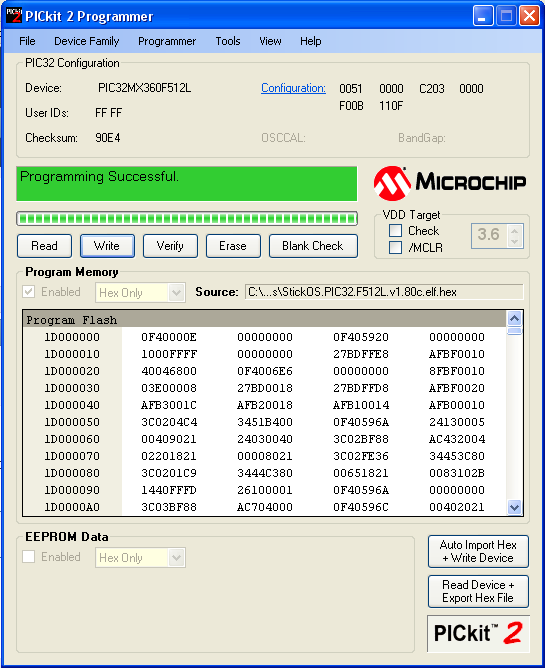
    Yes, MPLAB doesn't like the Pickit2 for use with PIC32, but who needs Mplab to load the Bitwhacker? All you need is the Pickit2 programmer IDE. I get the message saying "Programming Successful", and the command line interface I get after doing so. The Pickit2 is perfectly capable of programming PIC32 chips. Otherwise, it would not have a drop down menu including them. I don't quite know why MPLAB is forcing the use of other programmers, but you don't really have to worry about it.

    Name:  success.PNG
Views: 954
Size:  40.1 KB
    Last edited by ScaleRobotics; - 19th October 2010 at 17:07.
    http://www.scalerobotics.com

  2. #522
    Join Date
    Nov 2009
    Location
    Fitchburg, Mass
    Posts
    483


    Did you find this post helpful? Yes | No

    Default I get programming successful too, but

    My PICkit2 says it works, but the code is not embedded in the chip. I think the problem is with the size of the PIC32 memory. HIDbootloader goes near the front of memory. The high address is 4A20. StickOS goes higher up. StickOS gives me the warning when I try to download it. I have been able to load HIDbootloader, but have not been able to load the OS. At one point I think I got the OS loaded but in so doing it wiped out the bootloader. Of course this is all guess work.

    Ken

  3. #523
    Join Date
    May 2007
    Posts
    604


    Did you find this post helpful? Yes | No

    Default

    I would seriously look at alternatives to CPUStick/StickOS.

  4. #524
    Join Date
    Nov 2009
    Location
    Fitchburg, Mass
    Posts
    483


    Did you find this post helpful? Yes | No

    Default Yes, MikroBasic seems good.

    I enticed MikroBasic Pro to compile its 1st_project 'blink the LED's' Basic code . I then got PICKit2 to download the resulting .hex file.
    It seems that I can get freeware compiler, but I will be asked to spend $50 each for PICkit2 hardware and software. That is not as bad as the big bucks for PICBASIC PRO restricted to one PC machine per the license.

  5. #525
    Join Date
    May 2007
    Posts
    604


    Did you find this post helpful? Yes | No

    Default

    Another option I would highly recommend is Arduino, hardware is <$20 and software is free.

    Example hardware here Arduino Pro 328 - 5V/16MHz

    Name:  arduino.jpg
Views: 905
Size:  53.8 KB

  6. #526
    Join Date
    Nov 2009
    Location
    Fitchburg, Mass
    Posts
    483


    Did you find this post helpful? Yes | No

    Smile Arduino and some theory...

    There is a big write-up in the latest SERVO magazine on the advantages of Arduino. Maybe.....

    I've been thinking..... In my robocar I am controlling rates by measuring scalors. My PIC signals PWM to control rate of speed and rate of turn. Its sonar sensors are giving it distance. My code does not divide by time elapsed. ie differentiate. Is this a basically flawed concept?

    I have not been using the BASIC math operators. If I were to work in closing rates rather than pure distance would my error feedback be more appropriate?

    Ken

  7. #527
    Join Date
    Nov 2009
    Location
    Fitchburg, Mass
    Posts
    483


    Did you find this post helpful? Yes | No

    Talking Speed is the problem....

    I need help figuring how to control a robocar at speed. Simply said:

    The MODEL level car has proportional control. I preset the max velocity with a POT. I need a robo system that can figure out when to turn given the speed and the distance of oncoming obstacles.

    The TOY level cars have only bang-bang controls. Their tires are plastic. They slide and skid. The 1/12 scale car is slow enough for simple sonar distance threshold control. Boring!! The 1/10 scale car is a big fast colorful device: spectacular and fun! With size and speed comes momentum. I need to get better control of the steering (current drivers instead of DPDT relays?) and an algorithm to implement that control.

    Any ideas?

    Ken

  8. #528
    Join Date
    Nov 2009
    Location
    Fitchburg, Mass
    Posts
    483


    Did you find this post helpful? Yes | No

    Default Some robots map the room..

    Some robots first map their environment. If my car were to have a map of the room and could find its location, speed and direction in that room then given constant update of the robot's location and two dimensional velocity it ought to be able to maneuver the wall race. Any ideas how to implement such a scheme? I think the little car will need a compass or something similar. It sure would help if it knew the angle of its motion relative the four walls.

    Ken

  9. #529
    Join Date
    Nov 2009
    Location
    Fitchburg, Mass
    Posts
    483


    Did you find this post helpful? Yes | No

    Smile The answer is.....

    The solution is obvious for the MODEL level robocar.

    I made the wheel velocity proportional to the POT position. Stopping and turning distance requirements are proportional to speed. Make these distances proportional to the POT also. Easily done.

    I have no answer for the 1/10 TOY car aside from making it expensive by implementing a proportional control system.

    Ken

  10. #530
    Join Date
    Feb 2006
    Location
    Gilroy, CA
    Posts
    1,530


    Did you find this post helpful? Yes | No

    Default

    Hey Ken,

    I have heard you say bang-bang a lot describing the turning control for the car. Are you saying that with the remote control that came with the model car, there is no proportional control of the steering, just full right, straight, and full left? Or is there any in between?

    Perhaps you could do some testing to see if a pwm signal to the steering would give you some sort of proportional control?

    Is this the same for the throttle? On and off, and no in between? Perhaps you could test that as well.

    Without any more info, I don't think you can get more than wild guesses. Some pictures of the steering control, and motor control might help as well.

    EDIT: Hot off the press. This news from MeLabs:
    melabs now offers multi-seat, educational licensing of PICBASIC PRO for schools. Call for details.
    Last edited by ScaleRobotics; - 5th November 2010 at 16:45.
    http://www.scalerobotics.com

  11. #531
    Join Date
    Nov 2009
    Location
    Fitchburg, Mass
    Posts
    483


    Did you find this post helpful? Yes | No

    Default Yes, the toy cars have no proportional controls

    scalerobotics,

    1/10 scale TOY level cars cost about $50. 1/10 scale MODEL level cars start at $200. The TOYs are plastic toys. The MODELs are miniature automobiles.

    The TOY cars have only [full on / full off] steering and wheel power controls. Their steering servo has two inputs. Three of the four possible states are used:
    [A=7v, B=gnd] ==> steer left
    [A=gnd, B=7v] ==> steer right
    [A=gnd, B=gnd} ==> steer straight (spring loaded)

    The corresponding is true for Forward, Reverse, Brake (due to back EMF) for their DC drive motor.

    The TOYs have no differential gears, no drive gears at all, no toe in, no caster, no spring suspension, no dampening and plastic tires. They are inexpensive, fast, lots of fun and colorful. They do a great racing skid turn - just turn the wheel and put the motor in brake state. They are large enough to easily accommodate my solderless PIC kit.

    The 1/12 TOYs are considerably slower than the 1/10 size. I have succeeded in making one run smoothly around the room hugging the wall. A bit boring.....

    I'm off to the old gym to test my MODEL level with velocity and warning distances now all proportional to the position on one POT. Hopefully now all I need to do is find the correct velocity proportionizing formula for each of the SONAR warning distances which are:
    frontclear
    frontdanger
    stopreversing
    desiredtrack
    outertrack

    Ken

  12. #532
    Join Date
    Aug 2010
    Location
    Maryland, USA
    Posts
    869


    Did you find this post helpful? Yes | No

    Default

    heres my 2 cents. I think I read somewhere in this thread you are driving the steering/drives with actual relays. First thing to do I think is trade them in for H-bridges. Then you will be able to get much higher switching speeds.

    next, see if you can get the steering to become semi proportional or at least slower by pulsing the control. I am guessing it is a solinoid and not a motor for the steering. These take time to move fully, so if you can release the signal before the wheels have turned all the way, it will become at least stepped. the springs will smooth out the signals to make it appear proportional.

    Now I am sure you can do the same with the drive. Once you have H-bridges in there, you can PWM it
    -Bert

    The glass is not half full or half empty, Its twice as big as needed for the job!

    http://foamcasualty.com/ - Warbird R/C scratch building with foam!

  13. #533
    Join Date
    Nov 2009
    Location
    Fitchburg, Mass
    Posts
    483


    Did you find this post helpful? Yes | No

    Default You are correct...

    cmcmachineguy,

    You are correct. My TOYs use DPDT relays (6msec contact. 4msec release - so they say) driven by SN7407's I have been trying to avoid more electronics. I had hoped to have middle school students build the cars using solderless protoboards and to keep the cost down.... I may need to teach-the-teachers first. They did not major in Science, Technology, Engineering or Math in Ed School. Hmmmm.... In Massachusetts that means hooking up with a local college to give a course which teachers take for "professional development points".

    I did find that the TOY steering servos are slow to return to zero. A 50milsec kick to the opposite end gets them started. If I could figure a way to control the kick steer, that would be ideal. It is so spectacular.

    I am having a difficult time PIC controlling the MODEL car at cruising speed. This is no where near how fast I can make the car go around the track using the R/C, my eyesight and my coordination.

    I took it to the gym today with proportional SONAR thresholds implemented. BIG IMPROVEMENT but still it occasionally hit the wall. Don't know why yet......

    Thanks again for the interest and support.
    Ken

  14. #534
    Join Date
    Aug 2010
    Location
    Maryland, USA
    Posts
    869


    Did you find this post helpful? Yes | No

    Default

    Any way you can measure the current for the steering? Maybe it isn't real high and you can use 1 of the DIP H-bridge-on-a-chip. The stall current is what we are after here. Then you would still be able to easily proto board it. Leave the relay on the drive motors.

    I suspect if you can get the sterring under control, the drive will become less of a problem
    -Bert

    The glass is not half full or half empty, Its twice as big as needed for the job!

    http://foamcasualty.com/ - Warbird R/C scratch building with foam!

  15. #535
    Join Date
    Nov 2009
    Location
    Fitchburg, Mass
    Posts
    483


    Did you find this post helpful? Yes | No

    Default Radio Control cars are EVERYWHERE

    Today in the mail came two toy store Xmas catalogs. Both feature toy level R/C vehicles. All the more reason my autonomous car for introduction to STEM is a good idea. It may be that we need to teach-the-teachers first.

    On the subject of cost. In Fitchburg well over 50% of our public school students come from families that fall below the poverty line. In Massachusetts that means they are eligible for free or reduced price school lunches. If we were to use my cars to teach STEM to middle school kids, it would be nice if they could keep what they build. (Maybe in the context of an after-school program.) If we use my cars to guide teachers toward this corner of STEM through a college supported Professional Development course, again it would be nice if the students could keep what they build.

    Here's the question. What games can $50 1/10 scale TOY level cars play given the limitations of bang-bang controls and a 16F887 PIC. As a goal keep the total cost less than $100.

    Ken

  16. #536
    Join Date
    Nov 2009
    Location
    Fitchburg, Mass
    Posts
    483


    Did you find this post helpful? Yes | No

    Smile Wall racers -er SONARs - are expensive.

    The point of my project is communicating "how things work" to pre-teens.

    Examples of today's difficulties: My Mom's natural gas powered oven was obvious. Ever try to explain a micro-wave? Souping up a car in my day included high lift cams, carborator changes, tuned straight through pipes. Today the first thing you do to hop up a car is change a computer.

    The dashboard on my 2004 GM car told me: "TIRE Pressure LR 23psi LOW". It also said, "TIRE Pressure RR 28psi OKAY". I pumped up my left rear tire. Then the car told me,"TIRE Pressure LR 23psi LOW" and "TIRE Pressure RR 33psi OKAY". WHAT??

    The garage mechanic told me each tire valve contains a pressure gauge and enough of a computer to maintain a connection to the car's internal wireless network. A previous owner of my car had rotated the tires. The mechanic also told me that my car, depending of accessories, carries some twenty computers.

    It seems to me that the first question in the mind of a future STEM professional is, "How does this thing work?"

    Ken

  17. #537
    Join Date
    Nov 2009
    Location
    Fitchburg, Mass
    Posts
    483


    Did you find this post helpful? Yes | No

    Default success with the model level car.

    Today at the gym I got two speed levels to negotiate the wall racing. I have divided my POT's full motion into six steps, 0 - 5. 0 is slowest. 5 is fastest.

    Today speed 0 and 2 worked fine. Speed 5 crashed a bit. This evening I increased the proportionality multipliers relating POT position to distance thresholds.

    If I can get this car up to speed, imagine racing with more than one on the track.

    Ken

  18. #538
    Join Date
    Nov 2009
    Location
    Fitchburg, Mass
    Posts
    483


    Did you find this post helpful? Yes | No

    Smile New video with some details

    I've added a new video to youtube.


    Check it out and please give me your advice. I think the car is not responding as fast as it can. I can list an abbreviated version on my code. I may have some fundamental incorrect.

    Ken

  19. #539
    Join Date
    Nov 2005
    Posts
    51


    Did you find this post helpful? Yes | No

    Default

    Hi Ken
    I've been watching and reading this thread with great interest and I've got to admire and take my hat off to you for your persistence. Don't give up your nearly there.
    Have you used interrupt's in your code ?
    If you have not may be the pic cannot proeccess the comamnds quick enough to repsoned. having watching some other video clips they seem to responed really quickly travelling at high speed.
    I was thinking of trying my Nitro car but I think that would be to fast.

  20. #540
    Join Date
    Nov 2009
    Location
    Fitchburg, Mass
    Posts
    483


    Did you find this post helpful? Yes | No

    Default No interrupts in my code

    chuck et al,

    My code has no interrupts. It loops through poling the sonars many times per second. They flash a red led when poled. This is visible.

    I use HPWM to generate the controlling signals. This is a stretch. The spec calls for one pulse each 20 msec. With the standard oscillator the PIC can't go that slowly. I learned what works by trial and error.

    When controlling the car using R/C I can make it behave at faster speeds than the PIC can. Why? It might be that the feed back loop through my eyes and fingers is inherently better. My PIC code only works with distances. My eyes and brain work with distance and rate (of closing speed and steering).

    Want to see some code?

    Ken

  21. #541
    Join Date
    Nov 2009
    Location
    Fitchburg, Mass
    Posts
    483


    Did you find this post helpful? Yes | No

    Default One other thing

    I have been wondering whether the HPWM code starts fresh each time it is called. My system calls it after every SONAR poling. This is many times per second. Could it be that each time HPWM is called it pulls the output pit down in order to create a new pulse stream and in so doing screws up the pulse stream it had been sending.

    Ken

  22. #542
    Join Date
    Nov 2005
    Posts
    51


    Did you find this post helpful? Yes | No

    Default

    Ken yes I would like to see some of your code,
    I'm not sure about the HWPM resetting, If I understand correct the pic is monitoring the distance so when it comes close to the object this decreases the HPWM signal ? to reduce spped and turn the wheels at the same time ?
    Are you sure that the pic to calaculating the distance fast enough to react with the object ?

    I would say that interrupts would be able to act faster than the standard code. it would be nice if you could see how fast the HPWM command is reacting or so fast the pic is processing the data fast enough from the SONAR's

  23. #543
    Join Date
    Nov 2009
    Location
    Fitchburg, Mass
    Posts
    483


    Did you find this post helpful? Yes | No

    Default Here's some code

    Thanks everyone.

    The speed of PIC calculations can be judged by the rapidity of the flashing LED on the SONARs. My code just goes round and round. This is very visible when I run the car without its skin. It flashes so fast as to hardly be blinking. At least every 100 msec.

    Here's the action part of my code. If you like I can include the constants, pin selections etc.

    main:
    'pause 10 'Assure ringing from previous triggers: are gone.
    GOSUB triggers
    '-------------------
    CheckIfInDanger:
    IF rangefront < frontdanger THEN
    HPWM 1,Straight,50
    HPWM 2,Back,50
    PAUSE 250
    reversing = 1
    GOTO reverseoutoftrouble
    ' loop till this is secured
    ENDIF
    '-------------------
    tryleftturn:
    IF rangefront < frontfree THEN
    'something ahead - turn hard left.
    HPWM 1,Left,50
    HPWM 2,HalfForward,50
    steeringleft = 1
    GOTO main 'loop till this is secured
    ENDIF

    '-------------------
    goingforward:
    HPWM 1,Straight,50
    HPWM 2,Forward,50
    '-------------------
    keepgoingforward: '----Compare to right wall
    IF rangeright > outertrack THEN
    HPWM 1,QuarterRight,50
    ENDIF

    IF rangeright < desiredtrack AND oldrangeright < rangeright THEN
    HPWM 1,Straight,50
    ENDIF

    IF rangeright > desiredtrack AND oldrangeright > rangeright THEN
    HPWM 1,Straight,50
    ENDIF

    IF rangeright > desiredtrack AND oldrangeright < rangeright THEN
    HPWM 1,QuarterRight,50
    ENDIF

    IF rangeright < desiredtrack AND oldrangeright >= rangeright THEN
    HPWM 1,QuarterLeft,50
    ENDIF

    GOTO main
    '-------------------------
    reverseoutoftrouble:
    GOSUB triggers
    WHILE rangefront < stopreversing
    HPWM 1,Right,50
    HPWM 2,Back,50
    GOSUB triggers
    WEND

    IF rangeright > outertrack OR rangeright < desiredtrack THEN
    HPWM 1,Left,50
    steeringleft = 1
    HPWM 2,HalfForward,50
    ENDIF
    GOTO main
    '--------------------------

    triggers: ' Check three sonars and channel 3 signal.
    oldrangeright = rangeright
    ' produce 10uS trigger pulse (must be minimum of 10uS)
    LOW trigright
    HIGH trigright
    HIGH trigright
    HIGH trigright
    LOW trigright
    'zero could be legal below
    PULSIN echoright,1,rangeright 'measures the range in 10uS steps
    PAUSE 10 'Wait for ringing to stop - read SF05 spec.

    pulsf:
    oldrangefront = rangefront
    LOW trigfront
    HIGH trigfront
    HIGH trigfront
    HIGH trigfront
    LOW trigfront
    PULSIN echofront,1,rangefront ' measures the range in 10uS steps
    PAUSE 10

    Checkpot:
    ' I think Potread goes from 0 to 6.
    ADCIN PORTA.0, Potread
    Potread = Potread/37
    Forward = 105+Potread
    HalfForward = 105+(Potread/2) 'seems to work.
    Back = 95-Potread
    HalfBack = 95-(Potread/2)
    '----------
    frontdanger = 210 + Potread*55 '210-540, 14-36 inches
    stopreversing = 180 + Potread*25 '180-330, 12-22 inches
    frontfree = 700 + Potread*60 '700-1060, 48-70 inches
    desiredtrack = 180 + Potread*20 '180-300, 12-20 inches
    outertrack = 360 + Potread*15 '360-450, 24-30 inches
    '-----Below worked for Potread = 0and2. Not for 5
    'frontdanger = 210 + Potread*50 '210-510, 14-34 inches
    'stopreversing = 180 + Potread*25 'Fix backup confusion
    'frontfree = 700 + Potread*50 '700-1000, 48-72 inches
    'desiredtrack = 180 + Potread*12 '180-252, 12-16 inches
    'outertrack = 360 + Potread*12 '360-432, 24-28 inches
    '----------
    'record for posterity
    WRITE 2, WORD Potread
    WRITE 4, WORD frontdanger
    WRITE 6, WORD stopreversing
    WRITE 8, WORD frontfree
    WRITE 10, WORD desiredtrack
    WRITE 12, WORD outertrack


    '***********************
    checkchannel3:
    'works with four AA batteries pack.
    'Radio receiver puts pulses
    'on this line whenever the transmitter is turned ON.
    switchtoPIC = 2
    WHILE switchtoPIC >= 2
    COUNT channel3,65,switchtoPIC
    HIGH portc.0
    WEND
    LOW portc.0
    RETURN

    END
  24. #544
    Join Date
    Nov 2005
    Posts
    51


    Did you find this post helpful? Yes | No

    Default

    Thanks Ken I will have a read through your code to get to understand it

    Regards,
    Chuck

  25. #545
    Join Date
    May 2007
    Posts
    604


    Did you find this post helpful? Yes | No

    Default

    Ken, there are 2 issues that have not been addressed since the beginning of this project.

    1. The less serious of the 2 is your use of the hardware PWM module. R/C devices, such as servos and ESC's, expect a control pulse (typically 1-2mS) at about 50Hz. You can probably go lower to 30Hz or higher to about 100Hz and things should still work fine. However, a PIC16 with a 20MHz clock (which I believe you are using) will not go below 1220Hz (PR2=0xff). Even with an 8MHz clock the lowest is 488Hz (244Hz with a 4MHz click) and is still probably to high compared to the desired 50Hz.

    2. To get a closed loop control system to work correctly, you need more than a bunch of if-then-else statements. Ideally you want to use a PID controller. A proportional-integral-derivative controller (PID controller) is a generic loop feedback mechanism. It measures a process variable (e.g. temperature), and checks it against a desired set point (e.g. 100 degrees Celsius); it then attempts to adjust the process variable by changing a controller output (e.g. PWM signal to an electric heater) which will bring the process variable closer to the desired set point. Even a simple P (proportional only) controller would be much better than what you currently have.

  26. #546
    Join Date
    Nov 2009
    Location
    Fitchburg, Mass
    Posts
    483


    Did you find this post helpful? Yes | No

    Default Pid??

    I have been wondering whether I have a basic mistake in my feedback loop. I am measuring distance and adjusting rate of speed and rate of turn. Maybe I should be measuring rates not scalars

    This means differentiating. I would need to measure two distances a fixed time apart. Then do some subtraction. I do that a little bit in my code, when I include "oldrangeright" in my state machine, but since there is no consistency to my sample time...... Rate of turn is even less clear.

    Is this the PID flaw you are suggesting? What is the solution? What are the technical limitations? Will a 16F887 do the job? Do I need C code including appropriate libraries? I do not know how to start.

    Your comments about my PWM are true. I found what works by trial and error. To get 50hz would I need to install an outside oscillator? Might I somehow divide down the internal one?
    Ken

  27. #547
    Join Date
    Nov 2009
    Location
    Fitchburg, Mass
    Posts
    483


    Did you find this post helpful? Yes | No

    Default Upon further thought....

    I think you are telling me that I have not been using my PWM mechanism. In the case of turning I have defined STRAIGHT QuarterRIGHT, HalfRIGHT, RIGHT and the corresponding for LEFT. (I did not show you folks my definitions.) But I only use STRAIGHT, RIGHT and LEFT. That's bang-bang like a TOY level car. I could be doing much finer adjustments if I did a bit more arithmetic on my SONAR readings. GOOD IDEA. GOOD OBSERVATION. Presently I do comparisons in HEX. I really don't want to waste time translating to decimal.

    Thank you!!

    Ken

  28. #548
    Join Date
    Nov 2009
    Location
    Fitchburg, Mass
    Posts
    483


    Did you find this post helpful? Yes | No

    Default measuring velocity??

    I can not imagine a cheapo device that will measure closing rate.

    Can a robot know closing velocity other than by measuring distances at specified time intervals and divide? Anybody seen this done with PBP (or C or C++) on a PIC? Is this the reason I will have to upgrade to a 32MX460? I would love to see sample code.

    Ken

  29. #549
    Join Date
    May 2007
    Posts
    604


    Did you find this post helpful? Yes | No

    Default

    Have you fixed the easier of your 2 issues yet? Expecting it to work correctly at 1220Hz when it is waiting for 50Hz may be a bit of a stretch. You can create a multi-channel, interrupt-driven, software PWM with a PIC16 and a 16-bit timer - such as TIMER1. If you don't know how to do that, then select a PIC18 and use DT's 2-CH Hardware Servo Driver (see CMS articles on the right of the HOME page). It is limited to only 2 channels but will work for your project for now.

    When you have that working correctly, then you can progress to the PID stuff which looks like this:
    Name:  TEST-6A.jpg
Views: 999
Size:  41.8 KB

  30. #550
    Join Date
    Feb 2006
    Location
    Gilroy, CA
    Posts
    1,530


    Did you find this post helpful? Yes | No

    Default

    Quote Originally Posted by rmteo View Post
    When you have that working correctly, then you can progress to the PID stuff which looks like this:
    Attachment 4944
    Hey RMTEO,

    Don't be shy about posting actual code. We would love to see your PBP example of the above.
    http://www.scalerobotics.com

  31. #551
    Join Date
    May 2007
    Posts
    604


    Did you find this post helpful? Yes | No

    Default

    Quote Originally Posted by scalerobotics View Post
    Hey RMTEO,

    Don't be shy about posting actual code. We would love to see your PBP example of the above.
    Hey SCALREOBOTICS,

    What made you think that I was going to do that in PBP? I do not think that PBP would be the way to go for Ken's situation but I would be happy to have you prove me wrong.

  32. #552
    Join Date
    Nov 2003
    Location
    Wellton, U.S.A.
    Posts
    5,924


    Did you find this post helpful? Yes | No

    Default

    Quote Originally Posted by rmteo View Post
    Hey SCALREOBOTICS,

    What made you think that I was going to do that in PBP? I do not think that PBP would be the way to go for Ken's situation but I would be happy to have you prove me wrong.
    Then why would you suggest that Ken do it? Other than to add more confusion or a chance to say something else is better.

    Why do you not post something to try helping. Always posting that another compiler is better is not a help. Other compilers might be better but that is not the issue here.

    So I will ask you to not to post on this forum if that is all you have to say.
    Dave
    Always wear safety glasses while programming.

  33. #553
    Join Date
    Feb 2006
    Location
    Gilroy, CA
    Posts
    1,530


    Did you find this post helpful? Yes | No

    Default

    Quote Originally Posted by rmteo View Post
    Hey SCALREOBOTICS,

    What made you think that I was going to do that in PBP?
    Uh ....... in case you didn't notice, this is a PicBasic forum. That would be what is spoken here. Each language that you recommend have their own forum. And we don't go there talking about PBP, do we?
    http://www.scalerobotics.com

  34. #554
    Join Date
    May 2007
    Posts
    604


    Did you find this post helpful? Yes | No

    Default

    Ken, good luck with your project.

  35. #555
    Join Date
    Nov 2009
    Location
    Fitchburg, Mass
    Posts
    483


    Did you find this post helpful? Yes | No

    Smile OKAY, gang, I get the picture

    rmteo's comments DO help. I went to WIKIPEDIA and looked up PID and pretty much understand what it is - sort of. It ain't so complicated as the single formulaic representation makes it appear.

    Question about PBP and my 16F887. I think the spec for my robocar says to produce one PWM pulse every 20 msec. Each pulse varying in width from 1 to 2 msec in 256 segments. A 1.5msec (created by 127 segments) pulse is neutral. In the case of my Electronic Speed Control anything above 1.5msec is FORWARD. Anything shorter than 1.5msec is BACK. What must I do to scale my chip's 4MHZ oscillator to accomplish this fete?

    What I am presently doing I came across by trial and error. I am not sure what shape the PIC is actually producing.

    Ken

  36. #556
    Join Date
    Nov 2003
    Location
    Wellton, U.S.A.
    Posts
    5,924


    Did you find this post helpful? Yes | No

    Default

    Dave
    Always wear safety glasses while programming.

  37. #557
    Join Date
    Nov 2009
    Location
    Fitchburg, Mass
    Posts
    483


    Did you find this post helpful? Yes | No

    Default Thank you for the October reference.

    I have not learned to SEARCH the forum.

    How about I return to basics. How about I make my controls interrupt driven. If had an interrupt routine that ran every 20msec, I could create a true-so-spec PWM signal and I could measure rate of closing speed for each SONAR. I think the 16F887 can get all my work done in 20msec. If not I can up the PIC power.

    Way back someone told me how to set up such an interrupt system. Where is that? It's Monday morning. Time to get moving.

    Ken

  38. #558
    Join Date
    Feb 2006
    Location
    Gilroy, CA
    Posts
    1,530


    Did you find this post helpful? Yes | No

    Default

    Here are some that were referenced in the thread. None of them use your chip though, so some modifications would need to be made, or changes to a new chip.

    A 12F683 design (would require a fair amount of changes to work on your chip)
    http://www.picbasic.co.uk/forum/show...4998#post84998

    This one could not be modified for your chip, and would require a 18F2431, or 4431.
    http://www.picbasic.co.uk/forum/show...1961#post91961 (cleaner code than above)

    And the one rmteo pointed out, which would require an 18 series chip: http://www.picbasic.co.uk/forum/cont...e-Servo-Driver (Darrels, so you can't really go wrong)

    Once you decide which way you would like to go, I am sure we can help you get it going.
    http://www.scalerobotics.com

  39. #559
    Join Date
    Nov 2009
    Location
    Fitchburg, Mass
    Posts
    483


    Did you find this post helpful? Yes | No

    Default changing PIC

    My video shows my kit uses a 0.1" centers solderless prototype board. If I am to change PICs I would like something compatible.
    I tried the 32BITWhacker board of 32MX460. I was disappointed because I could not program it using the PICKIT2 system. Maybe if I purchase a PICKIT3.....(It is programmable via its USB port. That requires I completely change my coding system and learn yet another variation of BASIC or C)

    What Microchip PIC do you all suggest that has a Dual Inline (DIP) configuration and is easily programmable?

    Ken

  40. #560
    Join Date
    Nov 2009
    Location
    Fitchburg, Mass
    Posts
    483


    Did you find this post helpful? Yes | No

    Default Not doing well picking a new PIC

    The BITwhacker is appealing because it has 0.1" center holes. All I need to do is solder male to male connectors and stick the whole shebang into a solderless protoboard. It is a bit large for the HPI SPRINT R/C car. I never got the BITwhacker to work. (I purchased two. One came with a teeny tiny slide switch in the wrong position. That led me on a wild goose chase which ended up with one BITwhacker losing its embedded STICKOS code. The other board is good as new, but now I am leery of the whole thing.

    Is there a MIcrochip and/or MicroEngineering Labs product that works in a predictable fashion with the BITwhacker?

    If not the above then I need the schematic of a starter kit showing how a powerful-enough-to-do-my-job DIP configured PIC is hooked up to either a classic USB port or the RJ11 Microchip USB adaptor. The I need a PC based compiler that will do the job and a programmer that will load the resulting code into the PIC.

    Suggestions??

    Ken

Similar Threads

  1. PBP Book
    By Bruce in forum Off Topic
    Replies: 83
    Last Post: - 4th October 2021, 12:55
  2. PBP Extensions, What are they?
    By PJALM in forum PBP Extensions
    Replies: 9
    Last Post: - 28th September 2021, 11:26
  3. Compiler differences between PBP 2.33 & 2.46
    By nikopolis in forum mel PIC BASIC Pro
    Replies: 3
    Last Post: - 2nd May 2006, 19:01
  4. Newby- PBP wont compile for 18F (MPLAB)
    By jd76duke in forum mel PIC BASIC Pro
    Replies: 1
    Last Post: - 17th December 2005, 23:30
  5. Making PBP code more modular
    By forgie in forum General
    Replies: 30
    Last Post: - 25th October 2005, 16:24

Members who have read this thread : 4

You do not have permission to view the list of names.

Posting Permissions

  • You may not post new threads
  • You may not post replies
  • You may not post attachments
  • You may not edit your posts