MIBAM (pronounced "My BAM")
Which stands for ... "Mirror Imaged Bit Angle Modulation"
An include module for PicBasic Pro.
http://www.pbpgroup.com/files/MIBAM/MIBAM.swf
After a year and a half of playing with this thing ... One statement from RadikalQ3 made all my problems go away.
Thank you Radikal dude!
Also many thanks to BCD for beta testing the module.
I really liked the name "BAM-BAM", but MIBAM is probably a more descriptive acronym, so I've changed it. No matter what you call it ... I think you'll find that My "BAM" ... was the sound of hitting the nail on the head. 
This module is a modification of the BAM (Bit Angle Modulation) idea presented by Artistic License.
For more information about BAM, it's blinking problem and how this program came to be, please see this thread ...
http://www.picbasic.co.uk/forum/showthread.php?t=7393
Click image for larger Interactive version.
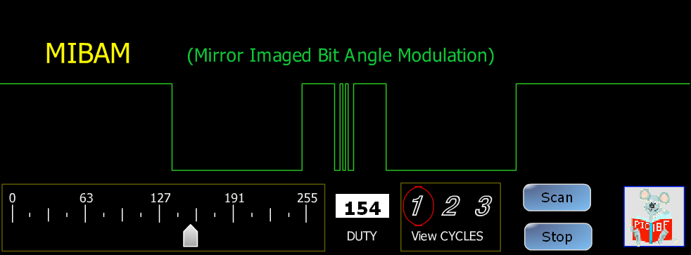
Click image for larger Interactive version.
What can it do?
Well ... it can turn almost every pin on your PIC into an LED dimmer. (limitations apply)
First, let's take a look at the basic MIBAM setup,
For an RGB LED (3 outputs) it might look like this ....
Code:
;----[ MIBAM Setup ]--------------------------------------------------------
BAM_COUNT CON 3                     ; How many BAM Pins are used?
INCLUDE "MIBAM.pbp"                 ; Mirror Image BAM module


RED    VAR BYTE
GREEN  VAR BYTE
BLUE   VAR BYTE


ASM
BAM_LIST  macro                     ; Define PIN's to use for BAM
     BAM_PIN (PORTB,0, RED)         ;   and the associated Duty variables
     BAM_PIN (PORTB,1, GREEN)
     BAM_PIN (PORTB,2, BLUE)
  endm
  BAM_INIT  BAM_LIST                ; Initialize the Pins
ENDASM
;_________________________________________________  __________________________
At this point, each BAM_PIN has been automatically set to OUTPUT, and the PINs will idle LOW until the Dutycycle variables are changed.
The Dutycycle range is from 0-255, 0 = OFF, 255 = brightest.
To change the brightness of an LED simply set the Dutycycle variable to the desired level.
You don't need to call any subroutines.
Here's an example of just fading the RGB LED's up and down.
Code:
Speed       CON 20   ; Smaller=Faster
Brightness  CON 200  ; Max DutyCycle

Main:
    FOR Red = 0 to Brightness -1          ; Ramp up 1 by 1
        PAUSE Speed
    NEXT RED
    FOR GREEN = 0 to Brightness -1
        PAUSE Speed
    NEXT GREEN
    FOR BLUE = 0 to Brightness -1
        PAUSE Speed
    NEXT BLUE


    FOR Red = Brightness to 1 STEP -1     ; Ramp down 1 by 1
        PAUSE Speed
    NEXT RED
    FOR GREEN = Brightness to 1 STEP -1
        PAUSE Speed
    NEXT GREEN
    FOR BLUE = Brightness to 1 STEP -1
        PAUSE Speed
    NEXT BLUE
GOTO Main
FOR loops always leave the variable 1 count further than the loop specifies.
when using direct FOR loops, you must account for the difference.
The module will work on most 16F's, ALL 18F's and some 12F's
If you are using a 14-bit PIC. You'll need to add these variables to your program for the Interrupt Context.
For 18F's you don't need to add these save locations. And they may cause errors if you do.
Code:
;____[ For 12F/16F only - Interrupt Context save locations]_________________
wsave       var byte    $20     SYSTEM  ' location for W if in bank0
;wsave       var byte    $70     SYSTEM  ' Alternate save location for W
                                        ' if using $70, comment out wsave1-3
' --- IF any of these next three lines cause an error ?? -------------------
'       Comment them out to fix the problem ----
' -- The chip being used determines which variables are needed -------------
wsave1      VAR BYTE    $A0     SYSTEM      ' location for W if in bank1
wsave2      VAR BYTE    $120    SYSTEM      ' location for W if in bank2
wsave3      VAR BYTE    $1A0    SYSTEM      ' location for W if in bank3
'---DO NOT change these-----------------------------------------------------
ssave       VAR BYTE    BANK0   SYSTEM      ' location for STATUS register
psave       VAR BYTE    BANK0   SYSTEM      ' location for PCLATH register
Limitations and Requirements- In order to use this module, you MUST be using MPASM for the assembler.
PBP's default PM.exe assembler will not work.
- This module takes over the Interrupts on the PIC because the timing of the waveforms must be exact.
With 16F's, You can NOT use any other interrupts, this includes ON INTERRUPT.
With 18F's, The module uses High Priority interrupts, and no other High Priority interrupts can be used.
Low priority Interrupts are available, but you still can NOT use ON INTERRUPT.
- The module uses Timer1, and it cannot be used for any other purposes.
Consequently, the PIC being used must have a Timer1.
- The number of LED's you can use is limited by the OSC frequency.
It's not that the module uses so much processor time that it needs more speed.
The limitation is the LSB (Least Significant Bit) of the DutyCycle, which is so short that it doesn't leave much time to do a whole lot of code.
@ 4Mhz, you can only run 4 LEDs MAX. This can be useful for RGB LED's on small chips.
@ 20Mhz, you can run 20 LEDs since there are more instructions available per period.
@ 48Mhz, you can run 48 LEDs, and anywhere in-between you can have the equivelant number of LEDs to match the OSC frequency.
If you attempt to use too many LEDs for a specific OSC frequency, the program will give a warning to indicate the results will be "Blinky".
- DO NOT overload your PIC.
A PIC can only source so much current. The specific amount is listed in the datasheet for the PIC you are using.
If you are driving a lot of LED's, you may need to buffer them with transistors or various other drive mechanisms.
Attached is the MIBAM.pbp module.
Download and unzip it to your PBP folder. (The one with PBPW.exe, usually C:\PBP)


Bookmarks