

I just noticed that the Xino Pro, which uses the same pin arrangements, has a pinout for the 18F25K20 on its web page. That should help in determining which PICs are compatible.


I just noticed that the Xino Pro, which uses the same pin arrangements, has a pinout for the 18F25K20 on its web page. That should help in determining which PICs are compatible.
What about jumpers? Add a little to the cost but it might be worth it in the long run.I2C presents one problem in that there's no way to easily deal with address conflicts should another shield also use I2C. I'll probably just tie all the address pins high with the leads exposed in such a way that the user can cut PCB traces to change the address.
Dave
Always wear safety glasses while programming.

or how about solder jumpers? No added cost at all.
-Bert
The glass is not half full or half empty, Its twice as big as needed for the job!
http://foamcasualty.com/ - Warbird R/C scratch building with foam!

The wait is over
http://blog.tibbo.com/
The new firmware was updated yesterday.
Regards
Ian
Thanks.Originally Posted by iwalker

Now I'm patiently awaiting the documentation and newsletter.
Perhaps. The time between laboratory and release with documentation varies from a few days to a few years. The product manager told me they had it working about 10 days ago so nothing is really new. I'll go back to patiently waiting.
Their web site has said for the other long supported EMxxxx modules that the 5 interface lines are (in essence) programmable. I just need confirmation that this is also the case for EM500.The module utilizes SPI interace and only requires five I/O line to control. Flexible mapping allows your application to use any five available I/O pins.
Last edited by dhouston; - 31st May 2011 at 17:14.
OK. I found the new firmware and documentation for the Tibbo. As soon as I'm satisfied with the details I'll get the prototype ethernet shield PCBs on order. They should be here within 2 weeks.
I can do the Tibbo testing. For ConnectOne, I have a nano LanReach but would have to solder headers to it to turn it into a nano SocketLan. I would rather not do that so I need volunteers to test all three ConnectOne modules. I'll give the volunteers an unpopulated PCB and maybe I'll install the SMT resistors and caps as I have those on hand. I cannot supply the rest.
I have a iL-SM2144N1-I with headers.
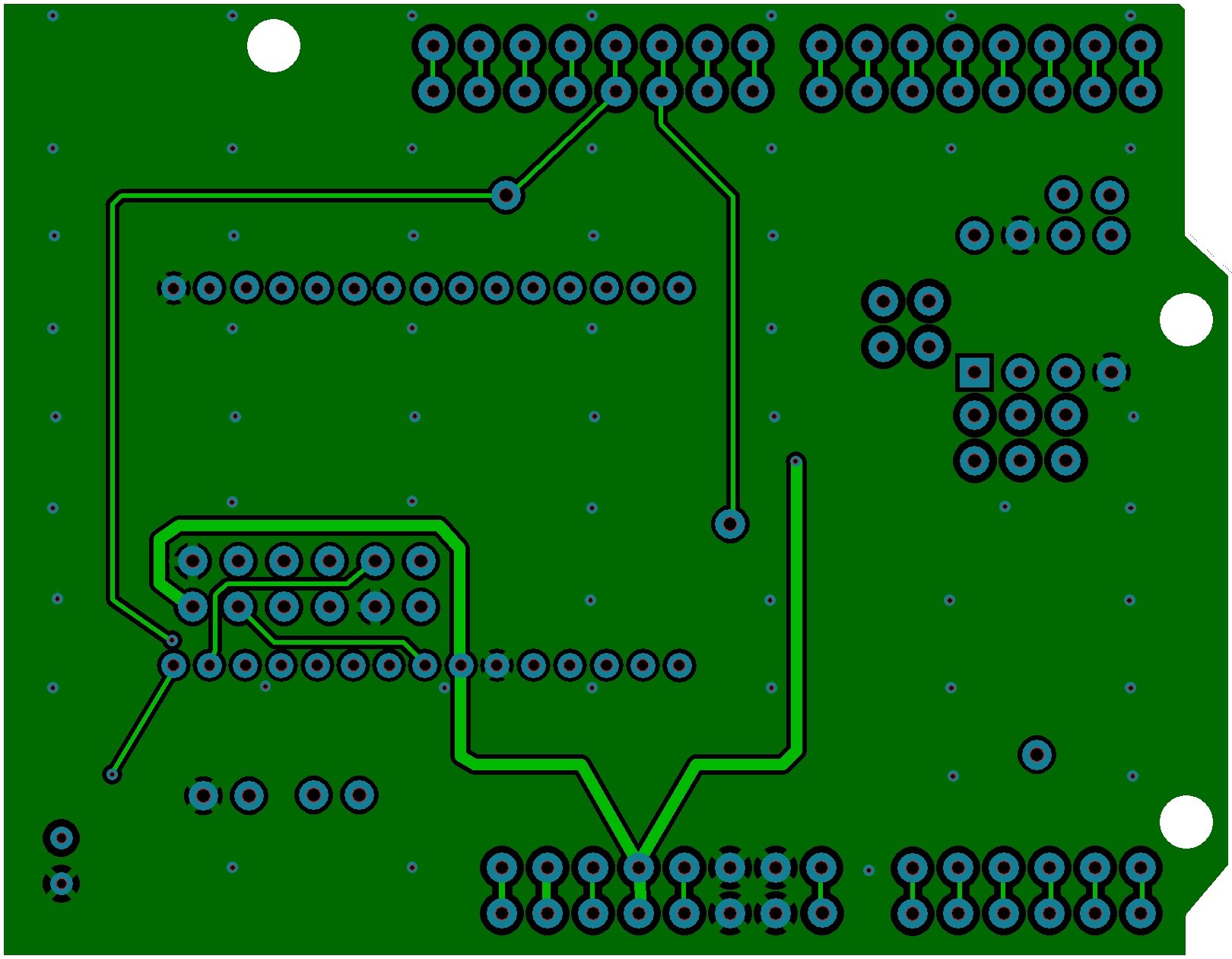
Something looks wrong on your board or maybe I have the wrong part or.... is the top view the bottom of the top view?
Dave
Always wear safety glasses while programming.
I've done a bit of both and also added through-hole pads to each of the five interface lines so they can be rerouted by cutting traces and adding wires.
One remaining issue - the socket for the mini iWiFi is taller than those for the other two modules.It's not a problem for end users but is for testing. I guess I'll have to find people with each who are willing to test and maybe write a short tutorial in exchange for one of the prototype boards.
Last edited by dhouston; - 31st May 2011 at 15:45.
Dave, I am in process of developing an embedded MCU application that will use the ConnectOne Mini iWiFi module. However, your use of the term "ethernet sheild" confuses me. By shield do you mean it provides an RF shield to protect the rest of the PCB containing the MCU from RF emissions? Is this PCB for use only with Arduino boards? Please explain so I know whether your "ethernet shield" would be of use to me.
I would also appreciate your comments regarding whether my PCB layout must take any specific precautions in the layout and grounding techniques to properly interface to the iWiFi via its 2x6 pin header. I am currently planning on creating a "copper pour" area on my PCB that lies under the overlying iWiFi module, but not sure what is really required. I am kind of new to trying to integrate an RF module with an embedded MCU PCB.
"Shield" is the term used for all of the boards designed to interface with the Arduino and its many clones - its derivation is a mystery to me.. So, yes, my ConnectOne shield is designed to work with Arduino system boards. You can see JPGs of my various shield layouts on my web site.
I usually leave as much copper as possible, both to help reduce EMI and to make the acid etchant last longer. Since the mini uses an external antenna, you will not need the clear area I provided for the onboard patch antenna of the nano.
Unless your application is a one-off design, it might be worth while to buy their evaluation board both for testing and to see how they handle the ground plane.
 Members who have read this thread : 0
You do not have permission to view the list of names.
 Posting Permissions


Bookmarks