

When a SCR is triggered it stays ON until the current drop to zero. TRIACs are 2 SCR doing a "69"to conduct both ways (AC).


When a SCR is triggered it stays ON until the current drop to zero. TRIACs are 2 SCR doing a "69"
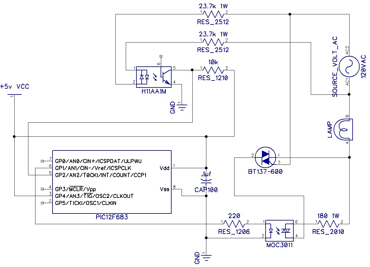
Hi guys got it to work. I am using an H11AA1 to detect the zero cross on the INT pin of the 12F673. From there I am using pauseus to hold the output pin off for x amount of microseconds. After the pause I turn on output pin which is driving an MOC3011 which in turn triggers the gate on the BT136. It is working quite well. I am not using a pot or anything to vary the delay. I want the light bulb to slowly brighten and then slowly dim for a lighthouse project.
I will upload the program I did once I clean up all the commented code I left in there while I was working on this. (probably clean that up tomorrow) in the meantime here it is operating

Good work. Nice demo
Thanks... sorry I called you Chris before I saw "Chris" instead of "Cheers" hahaha Anyway thanks.... I've got to clean up the code yet and draw up the schematic. Hopefully I will have some time later today to do that. Holiday weekend coming up so getting ready for that. I did add a little switch my father in law can switch and if he does the light will blink out "We love you dad" in morse code. I wanted it to say "Happy fathers day" but my wife vetoed that and said the latter. Bit late on fathers day I know but I got busy and had to order some of the components and they did not come in as fast as I needed them. I went back and reviewed some of the information I read about varying the phase and you are for sure right not sure how/why I got that backwards. Pretty cool little project does 60w lamp without getting warm using 1/2 watt resistors. I'm going to tweak those up to 1watt just in case. If you hold the 60w bulb on the on resistor gets just a tad warm but nothing you can't touch. 60w is going to be to bright for a little lighthouse but you never know with my father in law. I'll upload the code and schematic as soon as I have them done.
P.S. the 12F683 was not that bad to work with getting the INT pin set up. Actually got it right the first time. I had been running at 8mhz but no need took it back down to default 4mhz. There was no need to go 8mhz and use any extra power on it. I'm trying to conserve all I can I want this to run with a https://www.mouser.com/ProductDetail/490-PBO-1-S5 by my calculations 200ma should be more than enough for this and the other components without getting anything warm. I did not put it on there yet but hopefully will get to that today and test it out. I need to make this simple for my father in law just plug and play without external wall wart.
Regards
David
Last edited by DavyJones; - 3rd July 2020 at 12:10.
Sorry this took longer than expected. Hopefully I did not make any mistakes creating the schematic after the fact but I am pretty sure I did not. I'm using diptrace to produce the schematic and I've only used it a few times. Here is the picture of my schematic and code. This is working really good I've had it on for several days and have not seen anything going wrong however I am open to suggestions/criticism if anyone spots anything and wants to comment please feel free.
Regards
David
Attachment 8898Code:' LightHouse Lamp dimmer ' ====================== ' ' File name : Lighthousemorse.pbp ' Programmer : David C. Bittner ' Date : 2020-07-02 ' Device : PIC12F683 ' ' This program is use to dim intensity of an AC line load ' like lamp, motor and other. Developped for 60 Hz line. ' ' The software need : ' 1. A full wave signal from the AC line on GP2/INT ' TRISIO = %00101101 ' All input except GP1 GP4 GP1 out to TRIAC OPTION_REG.7=0 ' Enable pull-ups OPTION_REG.6=1 ' Interupt on rise CMCON0 = 7 ' Disable analog comparator ANSEL=0 ' Disable analog converter Triac var GPIO.1 ' Output to TRIAC gate ACLine var GPIO.2 ' Input for the FullWave rectify AC line morse var GPIO.5 ' used to check switch if 1 operate as dimmer, 0=morse out outp var GPIO.4 ' ' Variable definitions ' ===================+ ' TriacDelay var Word counter var word timercount var word updown var bit unit var word counter=0 unit = 500 TRIAC=1 'TEST TO MAKE SURE LIGHT COMES ON PAUSE 1000 'LEAVE IT ON FOR 1 SECONDS triac=0 pause 5000 ' wait 5 seconds before starting triacdelay=8000 ON INTERRUPT GOTO ACDetect INTCON=%10010000 ' Enable interrupt on GP2/INT change updown=1 '1=dim to bright, 0=bright to dim start: ' ' do what we need to in this routine if more ' if morse=1 then triac=1 outp=1 else outp=0 triac=0 gosub morsecode endif goto start morsecode: pause 2000 triac=1 ' W pause 400 'dot triac=0 pause 400 triac=1 pause 850 'dash triac=0 pause 400 triac=1 pause 850 'dash triac=0 pause 800 triac=1 'E pause 400 'dot triac=0 return ' ' ACDetect ' -------- ' ' Interrupt routine called by ACLine (GP2/INT) pin state change ' disable ACDetect: 'pauseus 240 counter=counter+1 if counter==5 then counter=0 if updown==1 then triacdelay=triacdelay-100 if triacdelay==-100 then 'triacdelay=8000 updown=0 endif endif if updown==0 then triacdelay=triacdelay+100 if triacdelay==8100 then updown=1 endif endif endif triac=0 pauseus triacdelay INTCON.1=0 resume enable
Last edited by DavyJones; - 7th July 2020 at 13:41. Reason: wrong picture
Can one of the mods change the title thread from "12F683 Light Dimmer Problem" to "12F683 Light Dimmer Problem (Solved)" I think that would be appropriate. Not sure if you can or not.
Regards
David
thank you
David
 Members who have read this thread : 0
You do not have permission to view the list of names.
 Posting Permissions

Bookmarks