

I'll ask again - why does my program leave the mainloop?
porta.1 goes high and low..continuously
OUTPUT PORTA.1
OUTPUT PORTA.4
HIGH PORTA.1
PAUSE 10000
mainloop:
LOW PORTA.1
HIGH PORTA.4
GOTO mainloop:
end


I'll ask again - why does my program leave the mainloop?
porta.1 goes high and low..continuously
OUTPUT PORTA.1
OUTPUT PORTA.4
HIGH PORTA.1
PAUSE 10000
mainloop:
LOW PORTA.1
HIGH PORTA.4
GOTO mainloop:
end
My dad never liked you...

You've writtenTry removing the colon as that's not supposed to there.Code:GOTO Mainloop:
didnt help..Originally Posted by HenrikOlsson

OUTPUT PORTA.4
OUTPUT PORTA.1
HIGH PORTA.1
PAUSE 10000
mainloop:
HIGH PORTA.4
LOW PORTA.1
GOTO mainloop
My dad never liked you...

a RESET could be a good explanation ...
Alain
************************************************** ***********************
Why insist on using 32 Bits when you're not even able to deal with the first 8 ones ??? ehhhhhh ...
************************************************** ***********************
IF there is the word "Problem" in your question ...
certainly the answer is " RTFM " or " RTFDataSheet " !!!
*****************************************

I'll ask again - why does my program leave the mainloop?
porta.1 goes high and low..continuously
its a classic RMW (read modify write error) i expect the load on porta.1 exceeds the
ability of the pic to maintain the logic level.
if your chip has latx regs use them
'OUTPUT PORTA.4
'OUTPUT PORTA.1
'becomes
out1 var lata.4
out2 var lata.1
trisa = % 11101101
'HIGH PORTA.1
'becomes
out2=1
PAUSE 10000
mainloop:
'HIGH PORTA.4
out1=1
'LOW PORTA.1
out2=0
GOTO mainloop
Warning I'm not a teacher
Hi, Richard
I tried this some years ago ... HIGH and LOW do not show the RMF " feature " ... even with a 3.3µF Tantalum capacitor as a load !
Alain
************************************************** ***********************
Why insist on using 32 Bits when you're not even able to deal with the first 8 ones ??? ehhhhhh ...
************************************************** ***********************
IF there is the word "Problem" in your question ...
certainly the answer is " RTFM " or " RTFDataSheet " !!!
*****************************************
try again with a red led and no resistor, i'm talking overloaded pin. HIGH and LOW do not show the RMF " feature " .
Warning I'm not a teacher
yout lat code worked but...
I used this
WDTE_OFF and it didnt come out of mainloop - worked
I also tried this
PWRTE_OFF - and I was able to write to my fet which had a load connected to it - didnt work right before I changed PWRTE_ON. (NOT SURE WHY)
Also - I know trisa = % 11101101 makes the inputs and outputs - but what does your code indicate? (why 8?)
I have this:
A0 - Led1 output
A1 - led2 output
A2 - Analog in
A3 - CLR
A4 - TTL Output to turn on FET
A5 - Input (TTL)
Ports C are all ttl inputs
can you help me set these registers up richard? -
VERY MESSY
OSCCON1=%00000011
OSCCON2=%00000011
INLVLA = %00000
INLVLC = %00000
TRISC = %11111 ' MAKE INPUTS
DEFINE OSC 4
OSCFRQ_4MHZ
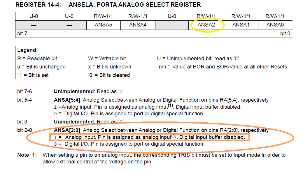
ANSELA = PORTA.2 ' MAKE ANALOG INPUT
ANSELC = %00000 ' MAKE DIPSWITCH INPUTS DIGITAL
Last edited by pescador; - 31st May 2023 at 23:05.
My dad never liked you...
Ports C are all ttl inputs
would be a bad move , st inputs are less susceptible to noise leave INLVLX as default
WDTE_OFF has no effect unless u had defined NO_CLRWDT 1
PWRTE_OFF
Clutching at straws and randomly poking at register settings is not a good solution
to noise induced issues and or defective code
ANSELA = PORTA.2 ' MAKE ANALOG INPUT
as pointed out by tumbleweed won't do anything like what you need
Warning I'm not a teacher
a pointless statement without the code that's in playit didnt come out of mainloop - worked
Warning I'm not a teacher
Here's what I need
A0 - Led1 output
A1 - led2 output
A2 - Analog in
A3 - CLR
A4 - TTL Output to turn on FET
A5 - Input (TTL)
PortC - dipswitch inputs - stable on or off.
My dad never liked you...
please email me if you can - easier to explain and I'd like to talk for 5 mins
Last edited by pescador; - 1st June 2023 at 00:05.
My dad never liked you...
all pic TRIS registers are 8 bits wide, the port pins are mapped onto those bits one for one , bits that don't match a pin do nothingAlso - I know trisa = % 11101101 makes the inputs and outputs - but what does your code indicate? (why 8?)
i cannot be bothered to look at the data sheet to see how many pins PORTA has on that chip so i play it safe and allow for all 8.
why 8 why not
putting you email on a public forum is not a wise move , i suggest you delete it pronto
pm me here on the forum if you have to
Warning I'm not a teacher
I need porta.2 to be a analog input - the rest are not analog - so how do I do that?
My dad never liked you...
no different to tris making pins input or output
Warning I'm not a teacher
PIC-AAAHH.pdf
see attached - I changed to LATs as suggested but I still cannot drive the base of my npn with the load in. If I remove the load and turn the FET on - its ok.
I dont get it.
#CONFIG
__config _CONFIG1, _FEXTOSC_OFF & _RSTOSC_HFINT32 & _CLKOUTEN_OFF & _CSWEN_ON & _FCMEN_ON
__config _CONFIG2, _MCLRE_ON & _PWRTE_OFF & _LPBOREN_OFF & _BOREN_ON & _BORV_LO & _ZCD_OFF & _PPS1WAY_OFF & _STVREN_ON
__config _CONFIG3, _WDTCPS_WDTCPS_11 & _WDTE_OFF & _WDTCWS_WDTCWS_6 & _WDTCCS_SC
__config _CONFIG4, _BBSIZE_BB512 & _BBEN_OFF & _SAFEN_OFF & _WRTAPP_OFF & _WRTB_OFF & _WRTC_OFF & _WRTSAF_OFF & _LVP_OFF
__config _CONFIG5, _CP_OFF
#ENDCONFIG


OSCCON1=%00000011
OSCCON2=%00000011


trisa = %11101100
trisc = %11111111


ANSELC = 0
ANSELA = 4


DEFINE OSC 4


FET var LATA.4 ' FET output
IG VAR PORTA.5 ' Ignition input
GREEN VAR LATA.0 ' TIMING LED
RED VAR LATA.1 ' FAULT LED


MAIN:
IF ig = 1 THEN
FET = 1
GREEN = 1
ELSE
FET = 0
GREEN = 0
ENDIF
My dad never liked you...
what is the load ?If I remove the load and turn the FET on - its ok.
what happens with a smaller load ??
sounds like power supply , noise suppression and or wiring layout is inadequate
Warning I'm not a teacher
DC electronic load - it works at 1 amp - any higher it fails (PIC cant drive the base).. no noise - PS can handle 20 amps.. The base of the npn must be sinking too much current for the PIC pin to drive at first. Whats strange is if I disconnect the load the PIC pin drives it ok, add the load and it keeps working. Power cycle PIC and it wont turn on the load again unitl I disconnect load and connect again.
My dad never liked you...
is this your complete code ?
Code:#CONFIG __config _CONFIG1, _FEXTOSC_OFF & _RSTOSC_HFINT32 & _CLKOUTEN_OFF & _CSWEN_ON & _FCMEN_ON __config _CONFIG2, _MCLRE_ON & _PWRTE_OFF & _LPBOREN_OFF & _BOREN_ON & _BORV_LO & _ZCD_OFF & _PPS1WAY_OFF & _STVREN_ON __config _CONFIG3, _WDTCPS_WDTCPS_11 & _WDTE_OFF & _WDTCWS_WDTCWS_6 & _WDTCCS_SC __config _CONFIG4, _BBSIZE_BB512 & _BBEN_OFF & _SAFEN_OFF & _WRTAPP_OFF & _WRTB_OFF & _WRTC_OFF & _WRTSAF_OFF & _LVP_OFF __config _CONFIG5, _CP_OFF #ENDCONFIG OSCCON1=%00000011 OSCCON2=%00000011 trisa = %11101100 trisc = %11111111 ANSELC = 0 ANSELA = 4 DEFINE OSC 4 FET var LATA.4 ' FET output IG VAR PORTA.5 ' Ignition input GREEN VAR LATA.0 ' TIMING LED RED VAR LATA.1 ' FAULT LED MAIN: IF ig = 1 THEN FET = 1 GREEN = 1 ELSE FET = 0 GREEN = 0 ENDIF
Warning I'm not a teacher
what voltage do you expect on the ignition input ?
is this expected to work in an automobile environment ?
Last edited by richard; - 1st June 2023 at 05:25.
Warning I'm not a teacher
with 6k in its collector and a hfe min of 100 the base current required is just a few microamps to drive it into saturationThe base of the npn must be sinking too much current for the PIC pin to drive
the pic will barely know its there
Warning I'm not a teacher
BTW ...
What kind of load do you intend to drive ???
Alain
************************************************** ***********************
Why insist on using 32 Bits when you're not even able to deal with the first 8 ones ??? ehhhhhh ...
************************************************** ***********************
IF there is the word "Problem" in your question ...
certainly the answer is " RTFM " or " RTFDataSheet " !!!
*****************************************
yes - thats my test code
My dad never liked you...
I should just say 12V, not IG - its 12V
My dad never liked you...
The schematic shows it drives 2 P channel Mosfets which supply power to a resistor load. - the 10k and 6k on the collector drive the gate when the npn is on.
The odd thing about this is when it powers up with resistor load attached - it will not drive the base of the npn. Release load and re-apply load - it stays on and works..
I tried this code this w same results - it tries to turn on the npn but cant, green led flutters on and off - release the load - green led turns on steady - re-apply load - it drives the npn. WTH...
MAIN:
FET = 1
GREEN = 1
GOTO MAIN
END
Last edited by pescador; - 1st June 2023 at 12:27.
My dad never liked you...
SCHEMATIC1 _ PAGE1.pdf
here's rough schematic again - sorry for the wild goose chase guys - really appreciate the help.
Q2 is only driving the gate of some P channel mosfets. With the load attached to the drain of the mosfets, pin 3 on PIC wont drive the base - the program leaves the main loop - it resets.
If I release the load and turn on NPN and then turn on load, it stays on.
I was aslo thinking of changing the circuit to a double npn and reverse the logic - thus the PIC wouldnt see the 2nd NPN, but I'd like to know why its behaving this way.
Last edited by pescador; - 1st June 2023 at 13:12.
My dad never liked you...
you are making this very difficult,
every schematic so far is different some are worse than others
the latest is doubtful r17 is too big 3k3 would be more realistic
this is very bad
given that vin high is vdd*0.8 and vin low is vdd*0.2
a 12 volt input lands slap bang in the middle nowhere land , the slightest bit of noise could swing it either way
r8 should be about 27k
you keep posting code snippets or incomplete fragments that are impossible to evaluate
this is a nonsense , and will continually reset because it has no loop it just wander off into lala land
i'm going to let it stew for a few days till you get your act togetherCode:#CONFIG __config _CONFIG1, _FEXTOSC_OFF & _RSTOSC_HFINT32 & _CLKOUTEN_OFF & _CSWEN_ON & _FCMEN_ON __config _CONFIG2, _MCLRE_ON & _PWRTE_OFF & _LPBOREN_OFF & _BOREN_ON & _BORV_LO & _ZCD_OFF & _PPS1WAY_OFF & _STVREN_ON __config _CONFIG3, _WDTCPS_WDTCPS_11 & _WDTE_OFF & _WDTCWS_WDTCWS_6 & _WDTCCS_SC __config _CONFIG4, _BBSIZE_BB512 & _BBEN_OFF & _SAFEN_OFF & _WRTAPP_OFF & _WRTB_OFF & _WRTC_OFF & _WRTSAF_OFF & _LVP_OFF __config _CONFIG5, _CP_OFF #ENDCONFIG OSCCON1=%00000011 OSCCON2=%00000011 trisa = %11101100 trisc = %11111111 ANSELC = 0 ANSELA = 4 DEFINE OSC 4 FET var LATA.4 ' FET output IG VAR PORTA.5 ' Ignition input GREEN VAR LATA.0 ' TIMING LED RED VAR LATA.1 ' FAULT LED MAIN: IF ig = 1 THEN FET = 1 GREEN = 1 ELSE FET = 0 GREEN = 0 ENDIF
Warning I'm not a teacher

if the problem is spikes, bad earth loop, filtering etc, then by posting here I feel it will ever be nailed down.
Can you post a video of the process, connections etc? Also an oscilloscope on that offending pin as you say that flatters, may show other things. Do you have an oscilloscope?
Ioannis
Is there a way to kill a thread?
My dad never liked you...
uncle.... do they have that expression down under? It means enough...
My dad never liked you...
see attached - do I own an oscillopscope I was asked? This is my proto lab.
I'm 67 years old who survived open heart surgery 4 months ago at NU hospital in Chicago, so not in the mood for rude comments.
I still do my own pcb layout, order boards, solder paste, pick and place machine, and IR oven my protos. And I attempt to do code using PIC Basic.
Yeah I was all over the place with my questions, my code constantly changed, my schematic was actually not correct in a few spots, which were actually corrected long ago - the V divider supplying 0-5V to my PIC input for example.
I did have a "goto main" in my code that was not shown by accident - getting a "its in lala land" comment.
I do apologize for being a bit scattered on this thread.
Last edited by pescador; - 2nd June 2023 at 01:54.
My dad never liked you...
Hi Pescador,
Take it easy ...
Some of us here live thousands miles away from you ... and don't know about the first bit of your programming or electronics design skills ...
So, the first of all things for us is to understand what you intend to build, how you want to proceed, and what you use to build it ... That implies a full description of the project and the problems encountered.
That also implies you have read carefully your PBP Manual ( THE Holy Bible ) AND the Pic Datasheet.
Not so simple and a crystal ball is THE most useful tool for about 90% ( 99% ? ) of the questions sent here ...
I easily understand it's a headache for you to find what is the real problem and you already have wasted hours scratching your head. We all lived that some day : that is called knowledge.
That said ...
a forum is a place where everybody can give an answer, considering everybody have its own fads ... beliefs and so on.
the answers may be right spot on or sending to la la land.
That's it and we must cope with that. Or rent highly skilled professionnals ... ( of course Fine advices : you've paid for it !!!)
Now ... just a bit of my story here ...
I was a contributor and one of the super Mods here, some years ago ( Yess ... ) , but some new guys ( other mods ) went here, thinking they knew everything and being God's children : kind of "knowledge war" where the strongest shouting was truth ... ( elders here just have a look towards Canada ... )
I simply preferred to come back to " simple forumer " status ... not having to re-demonstrate that 1+1 = 2 @ each time. Our discussions just led others to ... nowhere.
That to tell you everywhere somebody thinks he is the unique blessed owner of The Truth ... even believing he just helps !!!
BTW ... the one asking must also understand he is the unique one who knows what he has done ...
Back to your electronics problem ( it's NOT a programming problem ... for that you have shown here ...) just think how you can design the Pic supply to withstand some 100th of milliseconds main supply shut down ... without resetting
and you'll be fine.
Regards
Alain " the Frenchie "
Last edited by Acetronics2; - 2nd June 2023 at 07:21.
************************************************** ***********************
Why insist on using 32 Bits when you're not even able to deal with the first 8 ones ??? ehhhhhh ...
************************************************** ***********************
IF there is the word "Problem" in your question ...
certainly the answer is " RTFM " or " RTFDataSheet " !!!
*****************************************
You never said that you have a lab and tools to check signals. Also never showed the signal out of the PIC.
Asking if you have access to a tool is rude comment?
Being aggressive while we try here to help you does not really help at all.
After all, even if you received my comment as rude one, consider that we are spending time on this forum trying to help others. We may be located in countries too far away from mother america and our language may not be english. Do you really speak Greek?
Wish well recover and leave all the health problems in the past. But that does not make us rude people.
So, if you really want our help, as Alain said, please do give some details that we can understand your problem.
For one, you may show us the output pin of that PIC reseting as you suspect. Is it really reseting?
Ioannis
P.S. I am very happy that I am member of this extremelly helpful forum, for the wonderful giving people I happend to meat here and believe that there are no many forums with the quality we have here.
Last edited by Ioannis; - 2nd June 2023 at 08:45.
Hi, Ioannis,
How are you ???
That could be done just checking the dedicated bits of the processor, then powering small LEDS showing what happened.For one, you may show us the output pin of that PIC reseting as you suspect. Is it really reseting?
BUT that needs some more datasheet reading, and I do think our friend has to be led to Pic datasheet § 8.13 ... just for that checking.
It's a long way from idea to working device ... but you already know that
Best Regards
Alain
************************************************** ***********************
Why insist on using 32 Bits when you're not even able to deal with the first 8 ones ??? ehhhhhh ...
************************************************** ***********************
IF there is the word "Problem" in your question ...
certainly the answer is " RTFM " or " RTFDataSheet " !!!
*****************************************
Hi Alain.
All good! Thanks for your concern. Hope and wish for you too.
Well, pescador said that with the (strange) load he places on the output, the PIC seems to reset. So, that is why I asked for an oscilloscope to see what actually the PIC does on that pin while trying to change the state. It may reveal more that way, for example:
1. Previous state
2. New state
3. How long the new state is output
4. Is it overloaded as initially was suspected?
5. Is it tristated?
Ioannis
Last edited by Ioannis; - 2nd June 2023 at 10:36.
my main question is ... Why having chosen such " monster size " mosfets ???
1) Imagine some kind of Halogen lights as a load: the inrush current can easily overload the switching supply ...
2) have a look to the pic voltage regulator : no big caps around it ... so, no supply weakness could be dampened. ( switching supplies ALWAYS have load response time - enough to lead to a pic reset )
as everyting fine without heavy load , it's correlated to load inrush current ...
just need a test, powering the Pic with a small "Duracell" battery - say 4v5 - and the load with that big power supply ...
************************************************** ***********************
Why insist on using 32 Bits when you're not even able to deal with the first 8 ones ??? ehhhhhh ...
************************************************** ***********************
IF there is the word "Problem" in your question ...
certainly the answer is " RTFM " or " RTFDataSheet " !!!
*****************************************
Sure you have a good point on that.
Again, a scope can show all these problems, nail them down for good. Either Power supply or output or anything else.
Ioannis

Just a shot in the dark; when I design a power supply for my PICs, I isolate the 5v (or 3.3 or whatever) regulator with a 10 ohm resistor from 12v (or whatever) and place a 10 uF and 0.1 uF cap on the regulator input side. Then I put a 100 uF and 0.1 uF (and sometimes a 0.01 uF) parallel caps on the output side (5v side) of the regulator. In addition, there will be some distance between the regulator and the PIC. The VCC pin(s) get(s) an additional 0.1 uF cap to help filter any spikes. These larger electrolytic power supply caps add reserve when a brief power drain occurs, and the small disc caps filter noise. Microchip has released numerous Application Notes regarding power supply filtering and the importance of it. Just for kicks & giggles, give additional power supply caps a try and see if anything changes.
[I have a large periodical table of elements I hang in my work area. I write often-used formulas there, as well as a resistor color band chart. I made a note to "Add more filter caps" and "Add more test points on PCBs" on my table because of issues I've had in the past.]
totally agree and in an automotive enviro would make that 10 ohm R a RFC .
also for high current switched loads pcb layout and wiring design are crucially important
I have a suspicion about what the problem is, but I can't confirm it without knowing more detail. I'm not going to go out of my way on this just for the chance to learn later that that's not actually the problem and the goal posts have moved again.
Warning I'm not a teacher
Another trick you might try is to initialize your SFRs, but put a PAUSE 100 before activating anything. This will give time for the power supply to stabilize. You said if you turn it off and turn it on again it works. This would skip the first turn on and jump to the one that works.
 Members who have read this thread : 13
You do not have permission to view the list of names.
 Posting Permissions
 Reply With Quote
Bookmarks