


Hello all,
I need to measure the time between two different pulses leading edges.
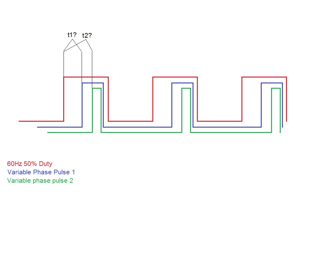
The trigger pulse is a 60 Hz square wave with a 8.228mS width, 50% duty that is currently being generated by another PIC, but could actually be generated by the PIC I want to do the measuring from to simplify things. It needs to be constantly running.
The second pulse varies in width by three different amounts, 555uS, 1.668mS and 3.33mS, but the width is unimportant to me, Im just trying to measure the time between the trigger pulses leading edge and the leading edge of this pulse. The second pulses leading edge always stays within the envelope of the first pulse.
I guess Im trying to measure the phase between the two?
I really need to do this on another, third, pulse as well, its the same as above, I just left it out of the explanation of my problem for claritys sake. It would be the green pulse in the included drawing
Ive searched around and found this post to be the most promising: http://www.picbasic.co.uk/forum/show...se+measurement
But Ive never used the CCP to measure anything or played with interrupts before.
It looks like what I may need with a few tweaks, but it would also be nice to generate the 60 Hz square wave pulse, trigger off of its leading edge and measure the time until the leading edge of the second pulse and third pulses all on one PIC
I need to spit the raw measurement out serially too. 2400 8N1 is fine.
I figure I would grab three readings of the first timing, average, and then three readings of the second timing, average it too and then spit the raw averaged numbers (t1 and t2) out via SEROUT as the measurement doesnt vary without me making it vary, so I know when to expect a change.
My preferred hardware for this project is a 16F648A running off a 20MHz canned oscillator, but if I could pull it off on a DIP chip with less pins, Im open to suggestions.
Any and all help is much appreciated!


Bookmarks