Trying to measure time between two pulses on different pins.


Closed Thread
Results 1 to 27 of 27

Hybrid View

  1. #1
    Join Date
    Sep 2006
    Location
    Indiana, USA
    Posts
    72

    Question Trying to measure time between two pulses on different pins.

    Hello all,

    I need to measure the time between two different pulses leading edges.

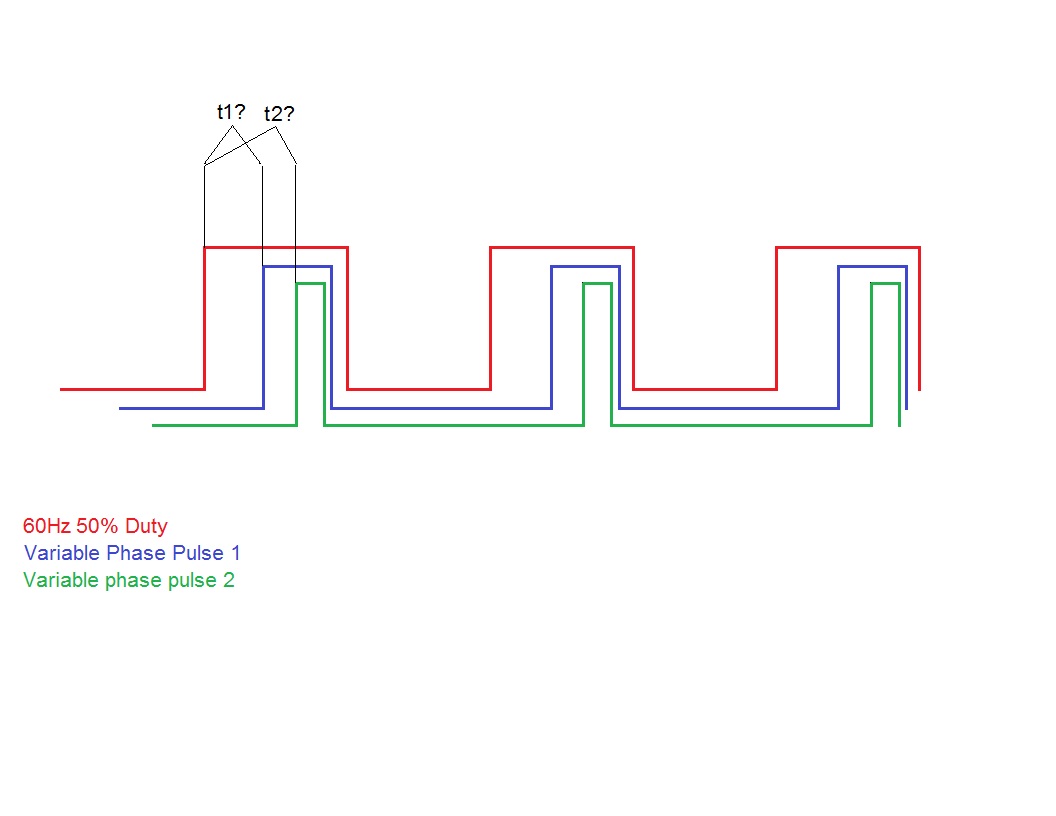
    The trigger pulse is a 60 Hz square wave with a 8.228mS width, 50% duty that is currently being generated by another PIC, but could actually be generated by the PIC I want to do the measuring from to simplify things. It needs to be constantly running.

    The second pulse varies in width by three different amounts, 555uS, 1.668mS and 3.33mS, but the width is unimportant to me, I’m just trying to measure the time between the trigger pulses leading edge and the leading edge of this pulse. The second pulses leading edge always stays within the envelope of the first pulse.

    I guess I’m trying to measure the phase between the two?

    I really need to do this on another, third, pulse as well, it’s the same as above, I just left it out of the explanation of my problem for clarity’s sake. It would be the green pulse in the included drawing

    I’ve searched around and found this post to be the most promising: http://www.picbasic.co.uk/forum/show...se+measurement
    But I’ve never used the CCP to measure anything or played with interrupts before.

    It looks like what I may need with a few tweaks, but it would also be nice to generate the 60 Hz square wave pulse, trigger off of its leading edge and measure the time until the leading edge of the second pulse and third pulses all on one PIC

    I need to spit the raw measurement out serially too. 2400 8N1 is fine.

    I figure I would grab three readings of the first timing, average, and then three readings of the second timing, average it too and then spit the raw averaged numbers (t1 and t2) out via SEROUT as the measurement doesn’t vary without me making it vary, so I know when to expect a change.

    My preferred hardware for this project is a 16F648A running off a 20MHz canned oscillator, but if I could pull it off on a DIP chip with less pins, I’m open to suggestions.

    Any and all help is much appreciated!
    Name:  Variable Phase Pulse.jpg
Views: 1584
Size:  53.3 KB

  2. #2
    Join Date
    Jan 2012
    Location
    Grid EN19MV
    Posts
    159


    Did you find this post helpful? Yes | No

    Default Re: Trying to measure time between two pulses on different pins.

    What if you were to use DT's Instant Interrupts? Have an interrupt that times out at some frequency - every time that interrupt happens, increment a counter. When the leading edge of the first pulse happens (could also be an interrupt), zero the counter. When the leading edge of the second pulse hits, read the counter and multiply by the frequency of the interrupt to determine the time.

    That was my first thought. Never actually done it - but I think it would work.
    Last edited by andywpg; - 21st August 2014 at 16:17. Reason: Spelling
    "I have noticed that even those who assert that everything is predestined and that
    we can change nothing about it still look both ways before they cross the street"


    -Stephen Hawking

  3. #3
    Join Date
    Sep 2006
    Location
    Indiana, USA
    Posts
    72


    Did you find this post helpful? Yes | No

    Default Re: Trying to measure time between two pulses on different pins.

    Wow, I am shocked speechless.

    I have used Darrel's gifts to the PBP world for years now. Most of what I have done with PBP has had some kind of help or influence from Darrel, if not robbing his code line per line. I had his instant interrupts in mind when I started fleshing out this latest pic based project and was hoping he might help me yet again, even though he didn't know who I was.

    I was just searching around to see if he was still active and came across the word that he has passed.

    Now I don't even know what to say.

    He was just an awesome person for helping so many people with the gift of knowledge. I could tell by his enthusiastic posts that it really made him happy to help out and gift his ideas to all of us.

    Even when I was at my wits end with a project, just reading his posts would help me push thru my problem. It also made me want to say thank you a million times over and be as nice as I could for all of you that have helped me. Real appreciation. This stuff isn't always easy, and to have someone so willing to guide the way was amazing.

    Darrel Taylor will be missed by a whole lot of people, and I think that says a lot for the guy.

    R.I.P DT!

  4. #4
    Join Date
    May 2013
    Location
    australia
    Posts
    2,389


    Did you find this post helpful? Yes | No

    Default Re: Trying to measure time between two pulses on different pins.

    a pic with timer1 gate control would be a perfect fit for this , eg 16f1825

  5. #5
    Join Date
    Oct 2005
    Location
    Sweden
    Posts
    3,521


    Did you find this post helpful? Yes | No

    Default Re: Trying to measure time between two pulses on different pins.

    Hi,
    Questions:

    1) Pulse 2 and 3 both falls within the envelope of pulse 1 but is pulse 3 always trailing pulse 2 or can it equally well be leading pulse 2?

    2) Once you've got your PIC doing these measurements, what else (if anything) do you need it to do?
    (I ask because quite often around here you come up with a possible implementation only to then get something like: Oh, that's great! Now I need to add this and that and..... - Which may render the initial idea and work useless.

    3) Will there always be two pulses or is it possible that one (or both) will be missing?

    Here's a bare bones aproach, it expects the pulses to be "in order" and there's no timeout or anything. Both can be easily accommodated for though.
    Code:
    Time1 VAR WORD
    Time2 VAR WORD
    Pulse1 VAR PortB.0
    Pulse2 VAR PortB.1
    Pulse3 VAR PortB.2
    
    Main:
    	GOSUB Measure
    	' Do whatever with the measurements
    Goto Main
    
    
    Measure:
    	T1CON.0 = 0		' Stop Timer
    	TMR1H = 0 : TMR1L = 0	' Clear timer
    
            While Pulse1 : WEND	' Wait until the 60Hz Square wave signal is low before "arming"
    
    	While Not Pulse1 : WEND ' Now wait for rising edge
    	T1CON.0 = 1          	' Start timer
    
    	WHILE Not Pulse2 : WEND	' Wait for leading edge of second pulse
    	Time1.HighWord = TMR1H
    	Time1.LowWord = TMR1L
    
    	While Not Pulse3 : WEND	' Wait for leading edge of third pulse
    	Time2.HighWord = TMR1H
    	Time2.LowWord = TMR1L
    RETURN
    /Henrik.

  6. #6
    Join Date
    May 2013
    Location
    australia
    Posts
    2,389


    Did you find this post helpful? Yes | No

    Default Re: Trying to measure time between two pulses on different pins.

    henrik
    is there a possibility of tmr1l rolling over after tmr1h read causing an error here ?

    and as you say will pulse 3 always lag pulse 2 . I also wonder what sort of resolution is required

  7. #7
    Join Date
    Oct 2005
    Location
    Sweden
    Posts
    3,521


    Did you find this post helpful? Yes | No

    Default Re: Trying to measure time between two pulses on different pins.

    Hi Richard,
    Yes there is. On some chips (not the 16F648 though, I believe) the timer is dubble buffered so you don't need to worry about it. On chips where it isn't you do need to cater for it by reading TMR1H "on both sides" of reading TMR1L and comparing the result to verify that it didn't roll over.

    As I said, the example is a bare bones approach. I didn't want to put too much into it before getting more details.

    /Henrik.

  8. #8
    Join Date
    Sep 2006
    Location
    Indiana, USA
    Posts
    72


    Did you find this post helpful? Yes | No

    Default Re: Trying to measure time between two pulses on different pins.

    Ok,

    Sorry I didn’t get back to my issue at hand. I was pretty bummed and just wasn’t feeling it yesterday.

    Anyway…

    I have two circuits that are identical. They are both clocked with a 60Hz, 50% duty, ~8.2mS pulse width +5 volt going square pulse. Low is 0V, high is 5V. They both need this signal all the time. So for now I’m just using a 12F675 to provide that signal.

    With that clock signal running, the two individual circuits each output a +5V square wave of their own, which by itself on a scope, doesn’t look like much but a square wave.

    But when you trigger a scope using the leading edge of the 60Hz, 50% duty pulse that the 12F675 is currently generating (and being provided to the clock inputs on the two circuits) and you have one of the other pulses on a second scope channel, you’ll see what is in my drawing, which shows just one circuits output for clarity.

    You have the 60Hz pulse with the other square wave nested inside of it. And if you adjust that circuit’s control, the pulse can be moved in relation to the steady 60Hz pulse. The other circuit is identical and does the exact same thing. And yes, it can lead the other circuits pulse (not the 60Hz pulse, both other pusles are always inside of the 60Hz pulse!) or fall behind it, or be right on top of it.

    My perfect solution for this would be:

    1. Generate the 60Hz 50% duty signal on one pin. Always running. HPWM10 maybe?

    2. Trigger a timer off of the leading edge of the 60Hz 50% duty signal (no clue, still haven’t messed with timers!!!)

    3. Count until the leading edge of the pulse from the first circuit comes in on a pin, hold that number in a variable.

    4. Repeat 2 and 3 a few times to build an average – hold that average in a variable.

    5. Trigger a timer off of the leading edge of the 60Hz 50% duty signal

    6. Count until the leading edge of the pulse from the second circuit comes in on another pin, hold that number in a variable.

    7. Repeat 5 and 6 a few times to build an average – hold that average in a variable

    8. Send the measurement from both average variables out via SEROUT.

    The future plan is to find out exactly what numbers to expect by spitting them out via SEROUT, once I know the ranges and such, I would build a lookup table using SELECT CASE or something and if the shift in a signal falls within a certain value, send a command out serially. This would be done for both circuits

    So: SEROUT serialPin, 4, [circuit1Data, circuit2Data…]

    The only timing in this that is critical is the 60Hz pulse must always be there, steady, constant. And of course the measurement itself need to be fairly accurate, with my lookup table I’m planning on building in hysteresis(?) like of

    circuit one's variable equals 225, my lookup would handle it as “if x = <230 AND <220 then” – or something like that just to cancel out minor errors.

    The signals I am measuring only vary by user input (i.e. turning a knob) and are independent of each other and will be handled by separate lookup tables, so measuring one before the other doesn’t matter, or if they both get measured at the same time. And seeing them change in any fine detail doesn’t matter either, So waiting on a routine to finish or something isn’t a big deal. Mainly its just getting an accurate measurement of the shift between the clock pulses leading edge and each circuits outputs leading edge.

    I’d like to do this all on one chip if possible. I was trying to think in terms of the 16F648A because I have them on hand and have used them quite a bit. I’m trying to stay away from having more pins than I need, so I really don’t want to have to use an 18F4550 or something. So if there is something around the same pin count as the 16F648A that can do all this in one chip, great. If not, I can live with the 12F675 and two 16F648A I guess.

    As always, thanks to all of you for helping me out!

    Respectfully,

    Ryan

    Name:  Variable Phase Pulse 2.jpg
Views: 1409
Size:  71.3 KB

Similar Threads

  1. Measure time in mS between two pulses
    By Fredrick in forum mel PIC BASIC Pro
    Replies: 8
    Last Post: - 7th March 2011, 07:20
  2. time measurement between 2 pulses
    By xvladx in forum mel PIC BASIC Pro
    Replies: 10
    Last Post: - 27th April 2010, 17:33
  3. calculate time between pulses
    By hell_pk in forum mel PIC BASIC Pro
    Replies: 19
    Last Post: - 20th October 2007, 16:49
  4. Count pulses between VARIABLE TIME
    By RodSTAR in forum mel PIC BASIC Pro
    Replies: 0
    Last Post: - 15th October 2007, 12:44
  5. Timed pulses on 2 pins
    By Danie Joubert in forum mel PIC BASIC Pro
    Replies: 1
    Last Post: - 15th March 2004, 07:38

Members who have read this thread : 1

You do not have permission to view the list of names.

Posting Permissions

  • You may not post new threads
  • You may not post replies
  • You may not post attachments
  • You may not edit your posts