My code below (using Darrels example to read VDD) is only displaying 65535 on my LCD???
This is on my breadboard with the PICkit2 supplying the 5vdc (4.87 measured w/voltmeter)
Any suggestions on why I am not seeing 4.87??
Code:
        '       Pic Configuration
        '       =================
#CONFIG
   __CONFIG _CONFIG1, _FCMEN_OFF & _IESO_OFF & _BOREN_OFF & _FOSC_INTOSC & _WDTE_OFF & _MCLRE_OFF & _PWRTE_OFF
   __CONFIG _CONFIG2, _LVP_OFF
#ENDCONFIG


' -----[ Initialization ]--------------------------------------------------
Reset:


        DEFINE OSC 4
        OSCCON    = %01101010
        TRISA     =   %001010                ' PortA.3 is button input, A.1 is a/d in
        ANSELA    =     %0010                ' Turn on Analog for AN1 (PortA.1)
        PORTA     = 0                        ' all outputs zero
        CM1CON0.7 = 0                        ' Disable comparator
        CCP1CON   = %00001100                ' CCP in PWM mode
        APFCON    = %00000001                ' Move PWM to PortA.5
ADCON0    = %00000111   'x,AN1,AD enabled

define adc_bits 10            'set up the a/d converter
define adc_clock 3
define adc_sampleus 50


        '
        '       Software variables
        '       ==================
    Duty    VAR WORD
    stepp   var byte
    Cmd     CON $FE        'LCD prefix for Command
    Clr     con 1          'LCD CLEAR SCREEN
    Hm      con 2          'LCD HOME COMMAND
    ADvalue var word
    VDD     var word

VDD_Res  CON 10              ; A/D resolution (bits) used for VDD measurement
FVrefMV  CON 1024            ; Fixed Vref Voltage in mV  ( must match FVRCON )
Vref_AD5 CON EXT             ; Calculate FVref A/D reading when VDD = 5.00V

@Vref_AD5 = (_FVrefMV*100000) / (500000000/(1023 << (_VDD_Res-10)))

        ' ----------------[ I/O Definitions ]-----------------------------------
        LED     var PortA.0              ' LED indicator
        Chg     VAR PORTA.2              ' FET to control charge current
        Btn     var PORTA.3              ' push button input
        Light   con 1                    ' Constant for HPWM channel 1 PortA.5


' -----[ Program Code ]----------------------------------------------------


pAUSE 500
SEROUT2 4,16468,[$1b,$2a,64]   'Set LCD backlight (0-255)
pause 200
SEROUT2 4,16468,[Cmd,Clr]       'clear LCD
pause 100


Main:
SEROUT2 4,16468,[Cmd,Clr]       'clear LCD
pause 100
gosub getvdd

Serout2 4,16468,[dec vdd,"   ",$0d,$0a]

pause 500
goto main


;----[Get VDD by reading the FVR]-----------------------------------------------
GetVDD:
    ADCON1 = %10110000       ; A/D Right Justified, FRC clock,VREF is VDD
    FVRCON = %10000001       ; Enable Fixed Voltage Reference (1.024V)
    WHILE !FVRCON.6 : WEND   ; Wait for fixed ref to be stable
    ADCIN 31, ADvalue        ; Read the FVR channel
    FVRCON = 0               ; Disable Fixed Voltage Reference
    VDD = Vref_AD5           ; calculated Vref A/D at 5.00V
    VDD = VDD * 500          ;   * 500  - two decimal places
    VDD = DIV32 ADvalue      ;   / FVRef reading - converts to VDD volts
RETURN
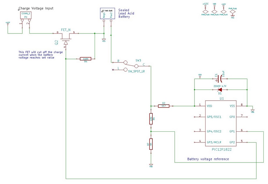
What I want to do is adapt this to read a 12V SLA (lead acid) battery that is also powering my PIC using a simple Zener Regulator(maybe not wise?)
How does one use the FVR to calibrate an external A/D reading of a 12v battery voltage via a resistor voltage divider??
My end goal is to have the PIC be able to cut off the charger when the battery reaches say 14.5 V for simple over charge protection.


Bookmarks