Watching for pin High


Closed Thread
Results 1 to 8 of 8
  1. #1
    Join Date
    Jan 2010
    Posts
    24

    Default Watching for pin High

    I am having trouble getting a program to run If statements when a pin goes high.

    I have a 16f628a for testing using three pins for outputs and four for inputs. Pins PortA.0 - PortA.3 are set low at the first of the program using:

    Low PortA.0 ect.

    The PCB has terminals when shorted send +5v to the inputs pulling them high.

    The main loop is such:

    :main
    If Porta.0 = HIGH then goto example1
    goto main

    When I pull the pin high, it doesn't do anything different. The rest of the pic and program is running fine sending out data when appropriate.

  2. #2
    Join Date
    Aug 2010
    Location
    Maryland, USA
    Posts
    869


    Did you find this post helpful? Yes | No

    Default Re: Watching for pin High

    Are you actually comparing porta.0 to "HIGH"? If so, try changing high to 1. High is a reserved word. You could also just say:
    If porta.0 then example1

    This will be true when the pin is high, and false when it is low.
    -Bert

    The glass is not half full or half empty, Its twice as big as needed for the job!

    http://foamcasualty.com/ - Warbird R/C scratch building with foam!

  3. #3
    Join Date
    Mar 2009
    Posts
    653


    Did you find this post helpful? Yes | No

    Default Re: Watching for pin High

    not familiar with that pic, but RA0 is shared with an analogue comparator, and the pin defaults to analogue so probably worth slapping in an...

    CMCON = 7

    to turn the comparator module off. (http://www.svetelektro.com/upload/16F628A.pdf page 64 upper right box)
    Last edited by HankMcSpank; - 15th October 2011 at 23:41.

  4. #4
    Join Date
    Oct 2005
    Location
    Sweden
    Posts
    3,521


    Did you find this post helpful? Yes | No

    Default Re: Watching for pin High

    What's been said and if you first do LOW PortA.0 the TRIS bit will be cleared so that the pin (RA0 in this case) is an output. When you then do If PortA.0 = 1 you aren't reading the state of the pin since it's not set to be an input.

  5. #5
    Join Date
    Oct 2009
    Location
    Utah, USA
    Posts
    427


    Did you find this post helpful? Yes | No

    Default Re: Watching for pin High

    Just to expand on what others have posted...
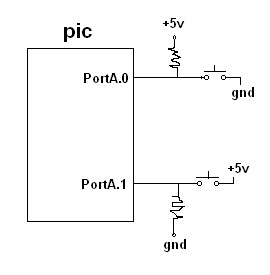
    Below is a schematic (sorry about the ugly resistors) that shows two different ways of wiring to detect a change on a port pin.

    First... with PortA.0 pulled high and a press on the button will cause a LOW or 0.

    Second... with PortA.1 pulled LOW and a press on the button will cause a HIGH or 1.

    The resistors can be 1K to 10K...


    Name:  2011-10-16_103005.jpg
Views: 317
Size:  8.5 KB

    It makes no difference and is not necessary to pre-set the state of the pin you are trying to test by "make port.pin LOW or HIGH" as that is an OUTPUT function not an INPUT function.

    The correct way is to choose one of the wiring options as illistrated, set the corresponding TRIS BIT for that port.pin to an INPUT or "1" and then test for the opposite state, which will indicate a change or button press.

    Code:
    TrisA= 000011   'set PortA.0 and PortA.1 as input
    
    IF PortA.0=0 THEN 'do something here when PortA.0 changes
    
    IF PortA.1=1 THEN 'do something here when PortA.1 changes
    as shown below... it is also correct to test for a "0" by testing for "NOT" and it is also correct to test for a "1" as shown...

    Code:
    IF NOT PortA.0 then '(this code tests for a "0" or "LOW")
    
    IF PortA.1 THEN ' (this code tests for a "1" or "HIGH"
    I hope this helps...

    PS... if you can not see the schematic image above, click on it.
    Last edited by Heckler; - 16th October 2011 at 17:33.
    Dwight
    These PIC's are like intricate puzzles just waiting for one to discover their secrets and MASTER their capabilities.

  6. #6
    Join Date
    Jan 2010
    Posts
    24


    Did you find this post helpful? Yes | No

    Default Re: Watching for pin High

    Thank you for the help. So far it is still not working(I have not tried everything suggested though). I will try to add the pull down resistors as well. I already have the working PCB but I should be able to drill and add them with some creative soldering.

    I didn't really intend this board to be an input board but figured I would use it for testing while I was ironing everything (output) else out.

  7. #7
    Join Date
    Jan 2009
    Location
    California, USA
    Posts
    323


    Did you find this post helpful? Yes | No

    Default Re: Watching for pin High

    Have you set the pins to be inputs using TRISA?

    (Heckler's post #5)

    Unless those pins are set as inputs, all other effort will be wasted...


    Steve
    Last edited by Byte_Butcher; - 16th October 2011 at 20:44.

  8. #8
    Join Date
    Oct 2009
    Location
    Utah, USA
    Posts
    427


    Did you find this post helpful? Yes | No

    Default Re: Watching for pin High

    actually the "TRIS" statement should have read...

    TrisA = %00000011 the "%" indicates the following number is binary

    you also need to turn off the comparators by including this statement...

    CMCON = %00000111
    or
    CMCON = 7 if you prefer to work with decimal numbers

    I like to show the configuration registers using binary as each bit usually does something different and it is easier for me to interpret my code.

    I am not sure of your level of knowledge setting up PIC micro's, but you should read the data sheet (at least parts of it) regarding the particular pins and functions you are trying to set up... for example TABLE 5-2 in the data sheet shows ALL the registers that affect PortA. There you see that CMCON must be configured to turn off the comparators.

    It is good to look around the forum and in the wiki section and view and study code examples to see how others set up the registers in order to do certain functions.

    That was by far the most difficult thing for me to understand when beginning to work with PIC's.

    As far as changing your circut board to include the pull-down resistor... you can also just hook it up externally without modifying your board. Just install a resistor (say 10K ohm) from the pin to ground... then when you touch that pin with +5 volts your code should be able to detect a "1".

    If you need more help... do post back here.

    good luck
    Dwight
    These PIC's are like intricate puzzles just waiting for one to discover their secrets and MASTER their capabilities.

Members who have read this thread : 1

You do not have permission to view the list of names.

Posting Permissions

  • You may not post new threads
  • You may not post replies
  • You may not post attachments
  • You may not edit your posts