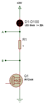
Hi There,
With the attached schematic, is it possible to read the current going through point A and Point B using any kind of PIC module?

Hi There,
With the attached schematic, is it possible to read the current going through point A and Point B using any kind of PIC module?

Last edited by sayzer; - 4th August 2010 at 10:56.
"If the Earth were a single state, Istanbul would be its capital." Napoleon Bonaparte
I think that's going to be a bit tricky because when the MOSFET is not conducting you'll basically have 24V at point A. Feeding that to a PIC input is a not a good idea.
You'd need a differential amplifier across the resistor. That will amplify the difference between point B and point A and you feed that signal to the PIC's ADC.
With that said, is there a reason for not having the current sense resistor on the low side? That would make it easier since it's then referenced to ground. With a low enough value resistor it shouldn't have any considerabl effect on the gate drive voltage but you would still need to amplify the signal. However, that too is easier than a differential setup.
/Henrik.
sayzer , Place the sense resistor in the lower leg of the fet driver to ground. Then the sensing voltage will be in reference to ground and the load voltage will be the same across the load. I would however place ~ 5.6 volt zener across the pic input pin to ground with a series 1K ohm resistor to the current sense resistor.
Dave Purola,
N8NTA
I appreicate the inputs.
I will drive the mosfet with PWM.
Thus, if I put a resistor to lower side, PWM will not be as good ( I think).
This is why I am trying to read the current on upper side.
Also, if I put ADC Vref(-) pin to Point B (on schematic), ADC input pin to Point A, how do I set up Vref(+)?
"If the Earth were a single state, Istanbul would be its capital." Napoleon Bonaparte
Hi,
Point B as Vref- was my initial thought as well. Then I noticed you're driving the thing with 24V and 24V on the PICs pin is not a good idea (the PICs Vss is still connected to ground, right). The internal clamp diodes will conduct and you'll likely destroy the PIC. You could limit the current going into the PIC with series resistor to prevent it from being destroyd but you'd still not get any reliable results.
Why do you think the PWM wouldn't work with the resistor "below" the MOSFET? As long as the resistance is low enough so that the MOSFETs Vgs is respected I can't see any problem with it.
It says 20A and 1ohm on the resistor, that's a 20V voltage drop across the resistor which is A LOT. If you're really driving 20A thru it somethiong like 0.05ohm would yield a voltage of 1V.
/Henrik.
HenrikOlsson,
Thanks for your input.
Schematic is just to show the concept.
As you said, I will use a 0.1 or 0.05 ohm resistor.
Based on my experiences, amateur experiences, PWM with direct gate drive ,is never the same as with a resistor (from Mosfet S to GND).
"If the Earth were a single state, Istanbul would be its capital." Napoleon Bonaparte
I've just joined so apologies to responding to older topics. Will respond to only topics where last responses that are within two weeks to prevent digging up 1-2 year old posts.
You can make a poor man's differential amplifier. Make a pair of voltage divider resistors so at 24V you have 5V at the center. Attach one from A to gnd and the other from B to ground. Feed the two signals into two ADC channels on a PIC, read them and subtract the values from each other. This will give you the voltage across the resistor therefore the current. Not knowing the expected current though the voltage levels may be too small without using a low Vref to the PIC.
I've done this with a high power adjustable current regulator where I have to monitor the voltage across the output load where one end is tied to 24V.
Bookmarks