Learning to walk again. (18F46J50 configuration)


Closed Thread
Results 1 to 27 of 27
  1. #1
    Join Date
    Jan 2009
    Location
    California, USA
    Posts
    323

    Default Learning to walk again. (18F46J50 configuration)

    OK, I'm trying to make an LED blink on a 18F46J50.
    I've done it (and more) successfully on several 16Fxxx chips, but this is my first "18F" experience, and boy this sucker sure has a lot of registers that want setting...

    So far I'm stumped with the CONFIG1L, CONFIG1H, and CONFIG2L registers. (oscillator control)

    When I attempt to set these particular 3 registers, I get syntax ERROR messages (I.E., ERROR Line 20: Syntax error.)

    Here, the OSCCON line compiles fine, but the 3 CONFIGxx lines do not.

    Code:
    OSCCON = %01111100      'idle enable off, 8MHz clock, primary clock source
    CONFIG1L = %11101100    'debugger disabled, no PLL divide, WDT off
    CONFIG1H = %11110111   'no memory code protect, no CPU clock divide
    CONFIG2L = %00000001   'osc out on RA6
    If I open the P18F46J50.INC file, I don't see any reference to any of those CONFIGxx registers in the register definition list.

    What am I doing wrong here that those 3 registers pop up with a Syntax Error?
    Could someone please help point me in the right direction..?

    Thanks!


    steve

  2. #2
    Join Date
    Jul 2003
    Location
    Colorado Springs
    Posts
    4,959


    Did you find this post helpful? Yes | No

    Default

    We should call that a 543 error.

    http://www.picbasic.co.uk/forum/showthread.php?t=543
    <br>
    DT

  3. #3
    Join Date
    Jul 2003
    Location
    Colorado Springs
    Posts
    4,959


    Did you find this post helpful? Yes | No

    Default

    OK, scratch that.
    That chip is one of the casualties of the __CONFIG has been depricated change.

    The old __CONFIG's won't work.
    Which means you can't put the configs in your program.
    It has to be done from the 18F46J50.INC file in your PBP folder.

    hth,
    DT

  4. #4
    Join Date
    Jan 2009
    Location
    California, USA
    Posts
    323


    Did you find this post helpful? Yes | No

    Default

    Thanks Darrel,

    That explains why my forehead is so sore.
    I've been pretty successful at setting up CONFIGs for 16F chips, using the good advice and techniques in Melanies excellent thread that you referenced.
    But no matter how many @'s and underscores and (or lack of) that I tried, I always get errors with this danged 18F46J50!

    THANK YOU for pointing out that it can't be done from within my program with this chip!!!! (well, that's damned inconvenient, ain't it?)
    I'll whittle away at it some more and post my results later.

    SO... does that mean that I've now got to maintain individual INCLUDE files for every project that uses this chip but doesn't use the same settings? THAT would totally suck...


    Thanks much!


    steve

  5. #5
    Join Date
    Jan 2009
    Location
    Miami, Florida USA
    Posts
    644


    Did you find this post helpful? Yes | No

    Default

    Byte_Butcher,

    Ok, I am just curious here. What type of programmer are you using? I never need to include the "__CONFIG" or the "@ DEVICE pic16F628, INTRC_OSC_NOCLKOUT" lines in my programs. I use the U2 Melabs programmer and it comes with software that takes care of all of this for you. You just change the settings in a pulldown menu and that's it. It's a lot easier and that way I don't make mistakes like forgetting to enter a setting or spelling issues, etc. I attached a picture of my programmer with settings for a PIC18F4550 for a USB project that I'm currently working on.

    http://store.melabs.com/prod/u2/U2.html

    Darrel,

    Will this software work for a 18F46J50? Or, do I need to use the inc file like you suggested to Byte_Butcher? Thank you.


    Robert
    Attached Images Attached Images  

  6. #6
    Join Date
    Nov 2003
    Location
    Wellton, U.S.A.
    Posts
    5,924


    Did you find this post helpful? Yes | No

    Default

    What about something like this in the code?
    Code:
    ASM
        CONFIG XINST = OFF
        CONFIG FOSC = HS
        CONFIG WDTPS = 512
        CONFIG CP0 = OFF
    ENDASM
    Dave
    Always wear safety glasses while programming.

  7. #7
    Join Date
    Jan 2009
    Location
    California, USA
    Posts
    323


    Did you find this post helpful? Yes | No

    Default

    Quote Originally Posted by rsocor01 View Post
    Byte_Butcher,
    Ok, I am just curious here. What type of programmer are you using?
    Robert, I''m using the PICkit 2.
    But the melabs programmer is starting to look pretty handy...

    Anyone else have any comments about using the melabs vs PICkit programmers?

    I've got what I think seem like intelligent configuration settings put into my 18F46J50 include file, but I STILL can't get an LED to blink. I don't think the chip is running at all.
    I'll post my code and configs later, after I've fed cats and taken care of some sunday morning chores.

    steve

  8. #8
    Join Date
    Nov 2003
    Location
    Wellton, U.S.A.
    Posts
    5,924


    Did you find this post helpful? Yes | No

    Default

    Quote Originally Posted by Byte_Butcher View Post
    Anyone else have any comments about using the melabs vs PICkit programmers?
    I have not used the melabs programmers, but over the years here it seems like one of the problems has been with the configs being set via the software. Problem solved by turning that feature of and learning how to set the configs in the *inc or in code space.

    You have a PicKit2, just stick with it.
    Dave
    Always wear safety glasses while programming.

  9. #9
    Join Date
    Jan 2009
    Location
    California, USA
    Posts
    323


    Did you find this post helpful? Yes | No

    Default Too many registers, not enough brain cells...

    OK, all I'm trying to do is flash 2 LEDs on ports B.4 and D.0 of the 18F46J50.
    It's not working. Not only do the LEDs not light, but the chip doesn't even seem to be running. All of the output pins seem to kind of "float" like they were high impedance inputs, and there's NO clock out on RA.6.
    I kind of get the feeling it's not running at all. I DO have 3.26 volts on both Vdd pins, and 2.44 volts on the Vcap pin (internal regulator), so the power is on.
    I'm guessing that there's SOMETHING that I haven't set correctly, but I haven't found it yet.

    Here's my CONFIG goodies. I'm trying to use the internal OSC with an output on RA6 so I can see if the clock is running.

    Code:
    ;****************************************************************
            NOLIST
        ifdef PM_USED
            LIST
            "Error: PM does not support this device.  Use MPASM."
            NOLIST
        else
            LIST
    ;;;        LIST p = 18F46J50, r = dec, w = -311, f = inhx32
            LIST p = 18F46J50, r = dec, w = -311
            INCLUDE "P18F46J50.INC"	; MPASM  Header
    
    	CONFIG XINST = ON
    	CONFIG STVREN = OFF
    	CONFIG PLLDIV = 2
    	CONFIG WDTEN = OFF
    
    	CONFIG CP0 = OFF
    	CONFIG CPUDIV = OSC1
    
    	CONFIG IESO = OFF
    	CONFIG FCMEN = OFF
    	CONFIG LPT1OSC = OFF
    	CONFIG T1DIG = OFF	
    	CONFIG OSC = INTOSCO  ;Internal OSC, with output on RA6
    	CONFIG DSBOREN = OFF
    	CONFIG DSWDTEN = OFF


            NOLIST
        endif
            LIST
    BLOCK_SIZE	EQU	64


    And here's my program.
    I was hoping that this would set the set the internal OSC to 8MHz, disable all the peripheral stuff, and flash some LEDS on ports B.4 and D.0
    No luck so far.

    Code:
    '****************************************************************
    'Test program to flash LEDS on PORTB.4 and PORTD.0 of the 18F46J50
    '****************************************************************
    
    Define OSC 8
    
    OSCCON = %01111111      'idle enable off, 8MHz clock, primary clock source
    
    '---PERIPHERAL CONFIGURATION REGISTERS---------------------------
    
    PPSCON = 0              'PERIPHERAL PIN SELECT INPUT REGISTER 0  --  0 = unlocked, 1 = locked
    
    '-------INPUT PIN SELECT-----------------------------------------
    RPINR1 = 27              'PERIPHERAL PIN SELECT INPUT REGISTER 1   ' SET ALL PERIPHERALS TO A NON-EXISTENT PIN (no peripherals selected on any pin)
    RPINR2 = 27              'PERIPHERAL PIN SELECT INPUT REGISTER 2
    RPINR3 = 27              'PERIPHERAL PIN SELECT INPUT REGISTER 3
    RPINR4 = 27              'PERIPHERAL PIN SELECT INPUT REGISTER 4
    RPINR6 = 27              'PERIPHERAL PIN SELECT INPUT REGISTER 6
    RPINR7 = 27              'PERIPHERAL PIN SELECT INPUT REGISTER 7
    RPINR8 = 27              'PERIPHERAL PIN SELECT INPUT REGISTER 8
    RPINR12 = 27             'PERIPHERAL PIN SELECT INPUT REGISTER 12
    RPINR13 = 27             'PERIPHERAL PIN SELECT INPUT REGISTER 13
    RPINR16 = 27             'PERIPHERAL PIN SELECT INPUT REGISTER 16
    RPINR17 = 27             'PERIPHERAL PIN SELECT INPUT REGISTER 17
    RPINR21 = 27             'PERIPHERAL PIN SELECT INPUT REGISTER 21
    RPINR22 = 27             'PERIPHERAL PIN SELECT INPUT REGISTER 22
    RPINR23 = 27             'PERIPHERAL PIN SELECT INPUT REGISTER 23
    RPINR24 = 27             'PERIPHERAL PIN SELECT INPUT REGISTER 24
    
    '-------OUTPUT PIN SELECT-----------------------------------------
    
    RPOR0 = 0               'PERIPHERAL PIN SELECT OUTPUT REGISTER 0  'SET ALL OUTPUTS TO THE "NULL" SETTING (no peripherals selected on any pin)
    RPOR1 = 0               'PERIPHERAL PIN SELECT OUTPUT REGISTER 1
    RPOR2 = 0               'PERIPHERAL PIN SELECT OUTPUT REGISTER 2
    RPOR3 = 0               'PERIPHERAL PIN SELECT OUTPUT REGISTER 3
    RPOR4 = 0               'PERIPHERAL PIN SELECT OUTPUT REGISTER 4
    RPOR5 = 0               'PERIPHERAL PIN SELECT OUTPUT REGISTER 5
    RPOR6 = 0               'PERIPHERAL PIN SELECT OUTPUT REGISTER 6
    RPOR7 = 0               'PERIPHERAL PIN SELECT OUTPUT REGISTER 7
    RPOR8 = 0               'PERIPHERAL PIN SELECT OUTPUT REGISTER 8
    RPOR9 = 0               'PERIPHERAL PIN SELECT OUTPUT REGISTER 9
    RPOR10 = 0               'PERIPHERAL PIN SELECT OUTPUT REGISTER 10
    RPOR11 = 0               'PERIPHERAL PIN SELECT OUTPUT REGISTER 11
    RPOR12 = 0               'PERIPHERAL PIN SELECT OUTPUT REGISTER 12
    RPOR13 = 0               'PERIPHERAL PIN SELECT OUTPUT REGISTER 13
    RPOR17 = 0               'PERIPHERAL PIN SELECT OUTPUT REGISTER 17
    RPOR18 = 0               'PERIPHERAL PIN SELECT OUTPUT REGISTER 18
    RPOR19 = 0               'PERIPHERAL PIN SELECT OUTPUT REGISTER 19
    RPOR20 = 0               'PERIPHERAL PIN SELECT OUTPUT REGISTER 20
    RPOR21 = 0               'PERIPHERAL PIN SELECT OUTPUT REGISTER 21
    RPOR22 = 0               'PERIPHERAL PIN SELECT OUTPUT REGISTER 22
    RPOR23 = 0               'PERIPHERAL PIN SELECT OUTPUT REGISTER 23
    RPOR24 = 0               'PERIPHERAL PIN SELECT OUTPUT REGISTER 24
    
    '-----------------------------------------------------------------------------------------------------------------
    
    TRISA = %00000000   'Set PORTA to outputs
    TRISB = %00000000   'Set PORTB to outputs
    TRISC = %00000000   'Set PORTC to outputs
    TRISD = %00000000   'Set PORTD to outputs
    TRISE = %00000000   'Set PORTE to outputs
    
    
    '---MAIN ROUTINE-------------------------------
    
    
    Main:
    
    PORTB.4 = 1
    PORTD.0 = 0
    pause 500
    PORTB.4 = 0
    PORTD.0 = 1
    pause 500
    
    
    goto main
    
    end
    Does anyone have any clues they could toss my way? In the meantime, I'll go RTFM some MORE in hopes I can make sense of all of those registers eventually...

    Thanks,

    steve

  10. #10
    Join Date
    Feb 2006
    Location
    Gilroy, CA
    Posts
    1,530


    Did you find this post helpful? Yes | No

    Default

    Edit: Err, I had a suggestion, but now I can't seem to get mine to work either. Let me regroup, and I will try to post something helpfull
    Last edited by ScaleRobotics; - 21st March 2010 at 16:48.

  11. #11
    Join Date
    May 2007
    Posts
    604


    Did you find this post helpful? Yes | No

    Default

    Take a look here on how to setup a similar device (ignore the RTCC stuff) http://www.picbasic.co.uk/forum/showthread.php?t=12553

  12. #12
    Join Date
    Jan 2009
    Location
    California, USA
    Posts
    323


    Did you find this post helpful? Yes | No

    Default From the "well duh" dept... GOT IT!

    Thanks everyone! I got it.

    Walter sort of put the clue in front of me. I took a look through that USB demo board data sheet, and when I got to the schematic of the thing I suddenly sat up and gave myself a good slap on the forehead! (DOH!)
    I took my soldering iron and stuck a 470 ohm resistor from Vdd to MCLR and now it works!

    I was so freaked out and worried about the huge pile of registers on this chip, that I forgot one of the most basic hardware items.

    LED's are blinking away now. Next job... get my LCD display to say "Hello World".


    Thanks to everyone for your help!

    steve

  13. #13
    Join Date
    Jan 2009
    Location
    California, USA
    Posts
    323


    Did you find this post helpful? Yes | No

    Default Still stumbling along, but I've almost got my feet under me... :)

    Wow, there's LOTS of "features" on a 18F46J50, and LOTS of registers and configuration thingies to set!
    And lots of RTFM'ing to be done to get this baby under control!

    Anyway, I've got far enough along to get the RTCC working and display the time to an LCD. Yay!
    Since there seems to be a shortage of info about the 18F46J50 here on the forum so far, I'll post my bit of working code. It's crude I'm sure, but it is functional and maybe it will be a helpful start for someone else.

    This code is enough to set up and turn on the RTCC module, using an external 32.768Khz xtal on the Timer1 Osc, and it displays the time on a 2 x 20 parallel LCD display.

    Here's my code, busted into 2 parts so it'll fit on the forum...

    Part 1: "Setup"

    Code:
    '****************************************************************
    '18F46J50 test program to turn on the RTCC and display time on a 2x20LCD
    '****************************************************************
    
    Include "MODEDEFS.BAS"   'Include Shiftin/out modes
    DEFINE LCD_DREG PORTD    'Set LCD Data port
    DEFINE LCD_DBIT 4        'Set starting Data bit (0 or 4) if 4-bit bus
    DEFINE LCD_RSREG PORTE   'Set LCD Register Select port
    DEFINE LCD_RSBIT 0       'Set LCD Register Select bit
    DEFINE LCD_EREG PORTE    'Set LCD Enable port
    DEFINE LCD_EBIT 2        'Set LCD Enable bit
    DEFINE LCD_BITS 4        'Set LCD bus size (4 or 8 bits)
    Define OSC 8             '8MHz Oscillator
    
    '---SET UP A BUNCH OF REGISTERS----------
    OSCCON = %01111111      'idle enable off, 8MHz clock, primary clock source
    ADCON0 = 0              'Turn OFF the ADC  
    ANCON0 = %11111111      'Analog Port Configuration bits (AN7-AN0) 1 = Digital, 0 = analog       
    ANCON1 = %00011111      'Analog Port Configuration bits (AN12-AN8) 1 = Digital, 0 = analog
    
    PMCONH.7 = 0            'Parallel Master Port Enable = OFF
    PMCONH.2 = 0            'Byte Enable Port Enable = OFF
    PMCONH.1 = 0            'Write Enable Strobe Port Enable = OFF
    PMCONH.0 = 0            'Read/Write Strobe Port Enable = OFF
    PMEH = 0                'PARALLEL PORT ENABLE REGISTER HIGH BYTE = OFF
    PMEL = 0                'PARALLEL PORT ENABLE REGISTER LOW BYTE = OFF
    
    RTCCFG = %10100100      'RTCC CONFIGURATION REGISTER ... sets up some of the RTCC stuff
    'RTCCAL = %00000000     'RTCC CALIBRATION REGISTER ... 0 = no adjustment
    PADCFG1 = 0             'PAD CONFIGURATION REGISTER  
    T1CON = %10001111       '
    
    TRISA = %00000000   'Set PORTA to outputs
    TRISB = %00000000   'Set PORTB to outputs
    TRISC = %00000000   'Set PORTC to outputs
    TRISD = %00000000   'Set PORTD to outputs
    TRISE = %00000000   'Set PORTE to outputs
    
    '---PERIPHERAL CONFIGURATION REGISTERS---------------------------
    
    PPSCON = 0               'PERIPHERAL PIN SELECT INPUT REGISTER 0  --  0 = unlocked, 1 = locked
    
    '-------INPUT PIN SELECT-----------------------------------------
    RPINR1 = 27              'PERIPHERAL PIN SELECT INPUT REGISTER 1   ' SET ALL PERIPHERALS TO A NON-EXISTANT PIN [27] (no peripherals selected on any pin)
    RPINR2 = 27              'PERIPHERAL PIN SELECT INPUT REGISTER 2
    RPINR3 = 27              'PERIPHERAL PIN SELECT INPUT REGISTER 3
    RPINR4 = 27              'PERIPHERAL PIN SELECT INPUT REGISTER 4
    RPINR6 = 27              'PERIPHERAL PIN SELECT INPUT REGISTER 6
    RPINR7 = 27              'PERIPHERAL PIN SELECT INPUT REGISTER 7
    RPINR8 = 27              'PERIPHERAL PIN SELECT INPUT REGISTER 8
    RPINR12 = 27             'PERIPHERAL PIN SELECT INPUT REGISTER 12
    RPINR13 = 27             'PERIPHERAL PIN SELECT INPUT REGISTER 13
    RPINR16 = 27             'PERIPHERAL PIN SELECT INPUT REGISTER 16
    RPINR17 = 27             'PERIPHERAL PIN SELECT INPUT REGISTER 17
    RPINR21 = 27             'PERIPHERAL PIN SELECT INPUT REGISTER 21
    RPINR22 = 27             'PERIPHERAL PIN SELECT INPUT REGISTER 22
    RPINR23 = 27             'PERIPHERAL PIN SELECT INPUT REGISTER 23
    RPINR24 = 27             'PERIPHERAL PIN SELECT INPUT REGISTER 24
    
    '-------OUTPUT PIN SELECT-----------------------------------------
    RPOR0 = 0               'PERIPHERAL PIN SELECT OUTPUT REGISTER 0  'SET ALL OUTPUTS TO THE "NULL" SETTING (no peripherals selected on any pin)
    RPOR1 = 0               'PERIPHERAL PIN SELECT OUTPUT REGISTER 1
    RPOR2 = 0               'PERIPHERAL PIN SELECT OUTPUT REGISTER 2
    RPOR3 = 0               'PERIPHERAL PIN SELECT OUTPUT REGISTER 3
    RPOR4 = 0               'PERIPHERAL PIN SELECT OUTPUT REGISTER 4
    RPOR5 = 0               'PERIPHERAL PIN SELECT OUTPUT REGISTER 5
    RPOR6 = 0               'PERIPHERAL PIN SELECT OUTPUT REGISTER 6
    RPOR7 = 0               'PERIPHERAL PIN SELECT OUTPUT REGISTER 7
    RPOR8 = 0               'PERIPHERAL PIN SELECT OUTPUT REGISTER 8
    RPOR9 = 0               'PERIPHERAL PIN SELECT OUTPUT REGISTER 9
    RPOR10 = 0              'PERIPHERAL PIN SELECT OUTPUT REGISTER 10
    RPOR11 = 0              'PERIPHERAL PIN SELECT OUTPUT REGISTER 11
    RPOR12 = 0              'PERIPHERAL PIN SELECT OUTPUT REGISTER 12
    RPOR13 = 0              'PERIPHERAL PIN SELECT OUTPUT REGISTER 13
    RPOR17 = 14              'PERIPHERAL PIN SELECT OUTPUT REGISTER 17  'CCP1 routed to RP17 (for the LCD contrast)
    RPOR18 = 0              'PERIPHERAL PIN SELECT OUTPUT REGISTER 18
    RPOR19 = 0              'PERIPHERAL PIN SELECT OUTPUT REGISTER 19
    RPOR20 = 0              'PERIPHERAL PIN SELECT OUTPUT REGISTER 20
    RPOR21 = 0              'PERIPHERAL PIN SELECT OUTPUT REGISTER 21
    RPOR22 = 0              'PERIPHERAL PIN SELECT OUTPUT REGISTER 22
    RPOR23 = 0              'PERIPHERAL PIN SELECT OUTPUT REGISTER 23
    RPOR24 = 0              'PERIPHERAL PIN SELECT OUTPUT REGISTER 24
    
    
     '---ALIAS PINS-------------------------
    RW              var     PORTE.1             'LCD READ/WRITE
    LED1            VAR     PORTB.4             'Blinky thing 1
    LED2            var     PORTD.0             'Blinky thing 2
    LCDcontrast     var     PORTC.6             'HPWM for LCD contrast
    
    '---ALLOCATE VARIABLES----------------- 
    contrast        var     word   'LCD contrast
    timevall        var     word                    'temporary storage for rtcvall
    timevalh        var     word                    'temporary storage for rtcvalh
    weekdaynum      var     word                    'Weekdaynum = 0-6  (0= sunday, 1= monday, etc)
    weekday         var     byte[9]                 'monday, tuesday, wednesday, etc
    year            var     word                    'year = 0 - 99
    month           var     word
    monthname       var     byte[3]                 'jan, feb, mar, etc                     
    day             var     word
    hours           var     word
    minutes         var     word
    seconds         var     word
    pmflag          var     word
    
    '---SET SOME VARIABLES-----------------
    RW = 0             'LCD R/W = Write
    led1 = 0           'Turn the LED off
    led2 = 0           'Turn the LED off
    contrast = 200     'Set LCD contrast (0-255) [0 = max contrast, 255 = min]
    
    '-----------------------------------------------------------------------------------------------------------------
    '-----------------------------------------------------------------------------------------------------------------
    end of part1....

  14. #14
    Join Date
    Jan 2009
    Location
    California, USA
    Posts
    323


    Did you find this post helpful? Yes | No

    Default

    Part2...

    Code:
    '-----------------------------------------------------------------------------------------------------------------
    '-----------------------------------------------------------------------------------------------------------------
    
    '---ENOUGH SETUP, LET'S GET STARTED................
    HPWM 1, contrast, 500   'set the LCD contrast
    Pause 1000   'wait for the LCD to wake up
    lcdout $fe, 1   'Clear LCD
    
    asm  ;This bit of code turns ON the RTC WRITE ENABLE. It MUST be done in ASM... RTFM- "16.2.7 WRITE LOCK", "SETTING THE RTCWREN BIT"
        movlb 0x0F ;RTCCFG is banked
        bcf INTCON, GIE ;Disable interrupts
        movlw 0x55
        movwf EECON2
        movlw 0xAA
        movwf EECON2
        bsf RTCCFG,RTCWREN
    endasm
    RTCCFG.7 = 1  'turn on the RTCC module
    
    '!!!!!!!!!!!!!!!!!!!USER SETTING!!!!!!!!!!!!!!!!!!!!!!!!!!!!!!!
    '---USER CAN SET THE CLOCK HERE----------------------------
    year = 10      '(last 2 digits of the millenium, 0-99)
    month = 03     '(1-12)
    day = 26       '(1-31)
    hours = 19     '(0-23)
    minutes = 29   '(0-59)
    seconds = 00   '(0-59)
    weekdaynum = 6 '(0-6)  (0=sunday, 1= monday, etc)
    '!!!!!!!!!!!!!!!!!//USER SETTING//!!!!!!!!!!!!!!!!!!!!!!!!!!!!!
    '----------------------------------------------------------
    
    Gosub settime 'put the user settings into the time registers
    RTCCFG.5 = 0   'disable RTC write enable
    
    goto main  'skip the subroutines and JGIG
    
    '--SUBROUTINES!----------------------------------------------------------------
    '---SUBROUTINE TO CONVERT USER ENTRY TO BCD AND LOAD THE TIME REGISTERS---------
    settime: '------(RTCPTR<1:0> automatically decrements by 1 each time RTCVALH is read or written to) RTFM, TABLE 16-3--------
        RTCCFG.1 = 1 'set RTCPTR1
        RTCCFG.0 = 1 'set RTCPTR0
        rtcvall = year dig 1 *16 + year dig 0  'set year
        rtcvalh = 00  'unused... just send something to rtcvalh so it will increment the pointer
        rtcvall= day dig 1 *16 + day dig 0  'set day
        rtcvalh = month dig 1 *16 + month dig 0 'set month
        rtcvall= hours dig 1 *16 + hours dig 0  'set hours
        rtcvalh = weekdaynum   'set weekday (0-6)
        rtcvall= seconds dig 1 *16 + seconds dig 0  'set seconds
        rtcvalh = minutes dig 1 *16 + minutes dig 0 'set minutes
    return
    '-----------------------------------------
    
    '---SUBROUTINE TO CONVERT THE BCD FOR EASY DISPLAY----------
    convertBCD:
        timevall = ((timevall/16)*10)+(timevall & %00001111)
        timevalh = ((timevalh/16)*10)+(timevalh & %00001111)
    return
    '------------------------------------------
    
    '---SUBROUTINE TO CONVERT MONTH NUMBER TO REAL TEXT-------------------
    decodemonth:   'there's GOT to be a better way to convert an index number to a string...
        if month = 1 then monthname[0] = "J": monthname[1] = "A": monthname[2] = "N"
        if month = 2 then monthname[0] = "F": monthname[1] = "E": monthname[2] = "B"
        if month = 3 then monthname[0] = "M": monthname[1] = "A": monthname[2] = "R"
        if month = 4 then monthname[0] = "A": monthname[1] = "P": monthname[2] = "R"
        if month = 5 then monthname[0] = "M": monthname[1] = "A": monthname[2] = "Y"
        if month = 6 then monthname[0] = "J": monthname[1] = "U": monthname[2] = "N"
        if month = 7 then monthname[0] = "J": monthname[1] = "U": monthname[2] = "L"
        if month = 8 then monthname[0] = "A": monthname[1] = "U": monthname[2] = "G"
        if month = 9 then monthname[0] = "S": monthname[1] = "E": monthname[2] = "P"
        if month = 10 then monthname[0] = "O": monthname[1] = "C": monthname[2] = "T"
        if month = 11 then monthname[0] = "N": monthname[1] = "O": monthname[2] = "V"
        if month = 12 then monthname[0] = "D": monthname[1] = "E": monthname[2] = "C"
    return
    '-----------------------------------------------------------------------------------
    '---[/subroutines]---------------------------------------------------------
    
    
    '-----------------------------------------------------------------------
    '---MAIN PROGRAM--------------------------------------------------------
    Main:
        '---set RTCPTR1 & RTCPTR2 to 11--- 
        RTCCFG.1 = 1  'set RTCPTR1 (RTCPTR<1:0> automatically decrements by 1 each time RTCVALH is read or written to) RTFM, TABLE 16-3--------
        RTCCFG.0 = 1  'set RTCPTR0
        
        '---get year---
        timevall = rtcvall
        timevalh = rtcvalh
        gosub convertBCD
        year = timevall
        
        '---get month and day---
        timevall = rtcvall
        timevalh = rtcvalh
        gosub convertBCD
        month = timevalh
        day = timevall
        
        '---get weekday and hours---
        timevall = rtcvall
        timevalh = rtcvalh
        gosub convertBCD
        weekdaynum = timevalh
        hours = timevall
        
        '---get minutes and seconds---
        timevall = rtcvall
        timevalh = rtcvalh
        gosub convertBCD
        minutes = timevalh
        seconds = timevall
        
        '---do the 24/12 hour dance---
        If hours > 11 then
            pmflag = "P"
            else
            pmflag = "A"
            endif        
        if hours > 12 then hours = hours - 12
        if hours = 0 then hours = 12
        
        gosub decodemonth
             
        '---display it all---
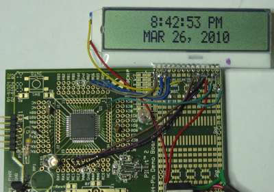
        lcdout $fe,2,"     ",dec hours,":",DEC2 minutes,":",Dec2 seconds," ",pmflag,"M  ",$fe,$c0,"    ",STR monthname\3," ",dec day,", 20",dec year
        pause 30 'Slow down you move too fast, You've got to make the morning last. Just skippin' down the cobble stones, Lookin' for fun and feelin' groovy
        
     goto main
    
    end
    end of part 2...
    Last edited by Byte_Butcher; - 27th March 2010 at 04:50.

  15. #15
    Join Date
    Jan 2009
    Location
    California, USA
    Posts
    323


    Did you find this post helpful? Yes | No

    Default

    And here's my configuration settings in the 18F46J50.INC file:

    Code:
    ;****************************************************************
            NOLIST
        ifdef PM_USED
            LIST
            "Error: PM does not support this device.  Use MPASM."
            NOLIST
        else
            LIST
    ;;;        LIST p = 18F46J50, r = dec, w = -311, f = inhx32
            LIST p = 18F46J50, r = dec, w = -311
            INCLUDE "P18F46J50.INC"	; MPASM  Header
    
    	CONFIG XINST = OFF
    	CONFIG STVREN = OFF
    	CONFIG PLLDIV = 2
    	CONFIG WDTEN = OFF
    
    	CONFIG CP0 = OFF
    	CONFIG CPUDIV = OSC1
    
    	CONFIG IESO = OFF
    	CONFIG FCMEN = OFF
    	CONFIG LPT1OSC = OFF
    	CONFIG T1DIG = OFF	
    	CONFIG OSC = INTOSCO  ;Internal OSC, with output on RA6
    	CONFIG DSBOREN = OFF
    	CONFIG DSWDTEN = OFF
    
    ;	CONFIG RTCOSC = INTOSCREF  ;Internal OSc for the RTC
    
    	CONFIG RTCOSC = T1OSCREF    ;RTCC uses T1OSC/T1CKI
    
            NOLIST
        endif
            LIST
    BLOCK_SIZE	EQU	64
    steve

  16. #16
    Join Date
    Nov 2003
    Location
    Wellton, U.S.A.
    Posts
    5,924


    Did you find this post helpful? Yes | No

    Default

    WOW! Thanks Steve.

    Now you have me thinking about trying the beast also
    Dave
    Always wear safety glasses while programming.

  17. #17
    Join Date
    Jan 2009
    Location
    California, USA
    Posts
    323


    Did you find this post helpful? Yes | No

    Default

    The obligatory photo of the test board and display:


    steve

  18. #18
    Join Date
    Jan 2009
    Location
    California, USA
    Posts
    323


    Did you find this post helpful? Yes | No

    Default

    Quote Originally Posted by mackrackit View Post
    WOW! Thanks Steve.

    Now you have me thinking about trying the beast also
    It's a big chunk of data sheet to read for sure. (554 pgs) It's a lot to absorb for someone of my... limited... skill level & experience.

    You won't have any trouble I'm sure Dave.

    I suppose the next step for me is to figure out how to make the USB work...


    steve

  19. #19
    Join Date
    Nov 2003
    Location
    Wellton, U.S.A.
    Posts
    5,924


    Did you find this post helpful? Yes | No

    Default

    USB is something I have not played with yet. It will be interesting to see how it goes.

    Keep us posted...
    Dave
    Always wear safety glasses while programming.

  20. #20
    Join Date
    Jan 2009
    Location
    Miami, Florida USA
    Posts
    644


    Did you find this post helpful? Yes | No

    Default

    This chip seems to be a nice upgrade to the more common USB-capable 18F4550. The 18F46J50 has 64 Kbytes of programming memory compared to 32 Kbytes of the 18F4550.

    Also, the 18F46J50 has a very interesting feature which is "On-Chip USB Transceiver with Crystal-less operation". Which means "High-Precision Internal Oscillator (±0.15% typ.) for USB", so no need for an external crystal oscillator . I will keep this chip in mind for my own projects.

    Now you have me thinking about trying the beast also

    USB is something I have not played with yet. It will be interesting to see how it goes.
    mackrackit,

    Even a rookie like me got the USB working on a 18F4550, so you shouldn't have any problems. But, I do recommend starting with a 18F4550 chip, which is a lot easier to work with and it is well documented in this forum. The 18F46J50 chip seems to be a lot harder to make it work.

    Robert

  21. #21
    Join Date
    Jan 2009
    Location
    California, USA
    Posts
    323


    Did you find this post helpful? Yes | No

    Default

    Quote Originally Posted by rsocor01 View Post
    Also, the 18F46J50 has a very interesting feature which is "On-Chip USB Transceiver with Crystal-less operation". Which means "High-Precision Internal Oscillator (±0.15% typ.) for USB", so no need for an external crystal oscillator . I will keep this chip in mind for my own projects.
    Only low speed USB (1.5 Mbps) is supported in "crystal-less mode".
    For full speed operation (12 Mbps) you'll need to use an external xtal.
    Still... not bad.

    And it's even got a RTCC calibration register that lets you "fine tune" the oscillator for the RTC.


    steve

  22. #22
    Join Date
    Jul 2003
    Posts
    2,405


    Did you find this post helpful? Yes | No

    Default

    Nice Steve. Where did you get the COG LCD display?
    Regards,

    -Bruce
    tech at rentron.com
    http://www.rentron.com

  23. #23
    Join Date
    Jan 2009
    Location
    California, USA
    Posts
    323


    Did you find this post helpful? Yes | No

    Default

    Quote Originally Posted by Bruce View Post
    Nice Steve. Where did you get the COG LCD display?
    Digikey.
    Steve likes Digikey.

    http://search.digikey.com/scripts/Dk...0220az&stock=1

    steve

  24. #24
    Join Date
    Jul 2003
    Posts
    2,405


    Did you find this post helpful? Yes | No

    Default

    Thanks.
    Steve likes Digikey.
    I bet Digikey likes Steve too ehh...;o)
    Regards,

    -Bruce
    tech at rentron.com
    http://www.rentron.com

  25. #25
    Join Date
    Jan 2009
    Location
    Miami, Florida USA
    Posts
    644


    Did you find this post helpful? Yes | No

    Default

    Quote Originally Posted by Byte_Butcher View Post
    I suppose the next step for me is to figure out how to make the USB work...


    steve
    Steve,

    Were you ever able to make the USB interface work in this 18F46J50 chip? Do you mind sharing your findings with us? I have been thinking about upgrading my 18F4550 to a 18F46J50.

    Robert

  26. #26
    Join Date
    Jan 2009
    Location
    California, USA
    Posts
    323


    Did you find this post helpful? Yes | No

    Default

    Sigh...
    I'm afraid I never got around to trying the USB. Most of my PIC projects are on hold for a while.
    Summer is here and I've got WAY too much work to do, plus a bit of machinery I'm trying to develop for the beverage industry (yeah, it's got a PIC), plus acres of weeds to be mowed, a garden to be tended, and a wife to take to doctor(s) appointments for cancer treatment.
    It's been a brutally busy spring for me and I haven't had time for any PIC related projects that don't have a specific (make money) goal in mind.

    I also broke down and got myself a little Taig desktop milling machine to make small parts to develop my "product" so that's currently eating up what little spare time I have during the week, learning to hack out nice little parts without breaking expensive carbide tool bits.

    Spring & summer months are always a low point for electronics projects for me, but when the rainy season gets here again around november my schedule should lighten up and I'll have time to switch back into "learning mode" again with the PIC's.

    I wish I had some good code to offer you, but I didn't get that far before spring got here....

    Steve

  27. #27
    Join Date
    Jan 2009
    Location
    Miami, Florida USA
    Posts
    644


    Did you find this post helpful? Yes | No

    Default

    Ooh, I'm sorry about your wife . I hope she gets better.

    I have been working on a USB project with a PIC18F4550, but I'm approaching the 32K program memory limit very fast. So, sooner or later I will give this 18F46J50 a try. If I make it work with the USB interface I will post some code in here.

    Robert

Members who have read this thread : 1

You do not have permission to view the list of names.

Posting Permissions

  • You may not post new threads
  • You may not post replies
  • You may not post attachments
  • You may not edit your posts