Here is my code:
Code:
Include "modedefs.bas"
INCLUDE "DT_INTS-14.bas"     ' Base Interrupt System
INCLUDE "ReEnterPBP.bas"     ' Include if using PBP interrupts
DEFINE     NO_CLRWDT    1
DEFINE          OSC     4       ' OSCCON defaults to 4MHz on reset

@ __CONFIG _XT_OSC & _WDT_OFF & _PWRTE_ON & _CP_ALL & _BODEN_ON & _CPD_ON

PAUSE 100
LED VAR PORTB.6
F1 var Bit
F2 var Bit
F3 var Bit
S1 var bit
S2 var bit
S3 var bit
i var byte

DEFINE DEBUG_REG PORTB
DEFINE DEBUG_BIT 7
DEFINE DEBUG_BAUD 2400
DEFINE DEBUG_MODE 1

DEFINE DEBUGIN_REG PORTA
DEFINE DEBUGIN_BIT 0
DEFINE DEBUGIN_MODE 1

PAUSE 50
ADCON1=7
CMCON=7
OPTION_REG=%10000111
TRISA=%000001
PORTA=0
TRISE=%000
PORTE=0
TRISB=%00000000
PORTB=0
TRISC=%00001111
PORTC=0
TRISD=%00000011
PORTD=0
CCP1CON=0
@ ERRORLEVEL -306

F1=0 : F2=0 : F3=0 : S1=0 : S2=0 : S3=0

main:
high LED: LED=1 : PAUSE 2000

ASM
INT_LIST  macro    ; IntSource,        Label,  Type, ResetFlag?
        INT_Handler   TMR1_INT,  _ToggleLEDF,   PBP,  yes
        INT_Handler   TMR0_INT,  _ToggleLEDS,   PBP,  yes
    endm
    INT_CREATE               ; Creates the interrupt processor
ENDASM
T1CON = $31                ; Prescaler = 8, TMR1ON
@ INT_ENABLE  TMR1_INT     ; enable Timer 1 interrupts
@ INT_ENABLE  TMR0_INT     ; enable Timer 1 interrupts'


while 1
Start:

M1A:
If PortC.0=0 then

mmm:
    for i=1 to 30
    DEBUG "MT3",2,10
   Pause 10
   next i

M1S:
   DEBUGIN 3000,mmm,[WAIT("MT3",2,"S")]
   F1=1 : PAUSE 1500

   DEBUGIN [WAIT("MT3",2,"C")]
   F1=0 : S1=1 : PAUSE 1500
endif

M1D:
  If PortC.1=0  then
mm:
   for i=1 to 30
    DEBUG "MT3",2,"D"
    Pause 10
   next i
   DEBUGIN 3000, mm,[WAIT("MT3",2,"D")]
  F1=0 : S1=0 : PortA.0=0  : PAUSE 1000
  endif
wend
'---[TMR1 - interrupt handler]--------------------------------------------------

ToggleLEDF:
     If F1=1 then Toggle PortD.2
     If F2=1 then Toggle PortD.3
     If F3=1 then Toggle PortC.4
@ INT_RETURN

'---[TMR2 - interrupt handler]--------------------------------------------------

ToggleLEDS:
TOGGLE LED
     If S1=1 then Toggle PortD.2
     If S2=1 then Toggle PortD.3
     If S3=1 then Toggle PortC.4'
 pause 100
@ INT_RETURN
I have to try many times by disconnecting/reconnecting the USB cable so that my board come to Green LED (Ready). 95% of times there is an error message. I am unable to do anything smoothly using this board, I do not know if I am doing somethign wrong or the board is faulty.
I am now trying to upload this code and errors is "Target Device does not match the selected device", even though 16F877A is selected on Programmer window.
Also with the ones I programmed before - My LED does not GLOW for 2 seconds when the code starts. PIC seems to keep resetting itself - The reason is that the LED starts flickering.
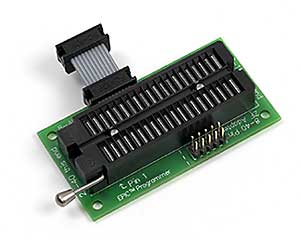
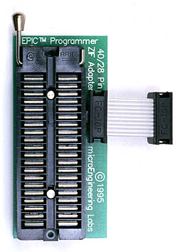
I am not programming the PIC while it is in its circuit. I am using the 40PIN connector with the USB programmer.
But First thing first, please help me solve the programming board problem, so I can firstly start programming smoothly. I have attached the programmer settings screenshot. Please let me if any more information is needed. Thanks a lot.


 -
- 


Bookmarks