144 LED Games Console Project


Closed Thread
Page 1 of 3 123 LastLast
Results 1 to 40 of 104
  1. #1
    Join Date
    Aug 2003
    Posts
    985

    Default 144 LED Games Console Project

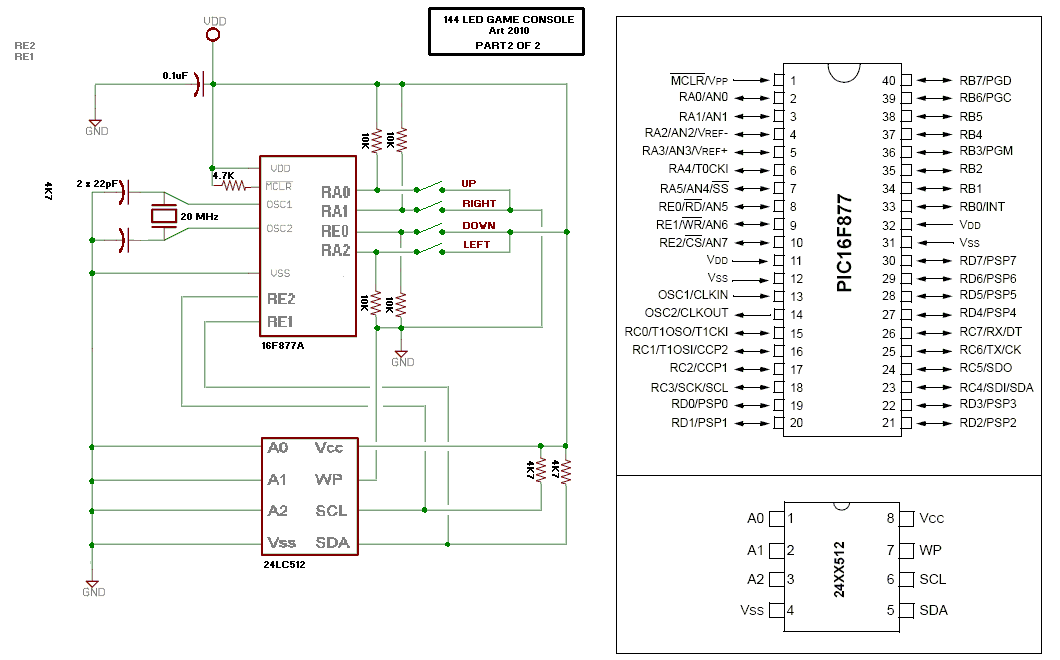
    144 LED Game Console
    Featuring original recoded clones of two classic games: Snake and Tetris!
    Art 2010 -------------------- Note: This is not an official Tetris product.

    144 LED Game Console - Bill Of Material

    001 x Microchip Pic 16F877 or 16F877A microcontroller
    001 x 40 pin DIL socket
    018 x BC549C or similar Transistors
    145 x LEDs (144 of one colour, and 1 of another for the power/error indicator)
    001 x 20 MHz Crystal
    009 x 330R Resistors
    018 x 1K2 Resistors
    004 x 10K Resistors
    001 x 4K7 Resistor
    002 x 22pF Disc Ceramic Capacitors
    001 x 0.1 uF Monolythic Capacitor
    001 x Prototype Printed Circuit Board (display)
    001 x Small Prototype Printed Circuit Board (joypad)
    004 x Momentary Push Buttons


    Display schematic is made from a modified version of a display by B.Morse.

    See YouTube Demos of the Games Here:
    http://www.freewebs.com/defxev/scroll.htm

    Code for the Microcontroller is coming soon!

    PS. If someone would like to make a PCB layout, that would be cool

    Cheers, Art.
    Attached Images Attached Images  
    Last edited by ScaleRobotics; - 26th June 2010 at 14:47. Reason: added Art's new schematic

  2. #2
    Join Date
    Aug 2003
    Posts
    985


    Did you find this post helpful? Yes | No

    Default

    Here's the schematic you'll need if you want to use the message scroller.


    The readme, hex file, and source code are posted in the attachment.
    Cheers, Art.
    Attached Files Attached Files

  3. #3


    Did you find this post helpful? Yes | No

    Default

    If you're into building things like this you might want to check out TI's line of LED drivers: http://focus.ti.com/paramsearch/docs...ODE_STRY_PGE_T
    National also has a great section on LED power:http://www.national.com/analog/led/high_brightness
    Maxim has a bunch of really cool led drivers as well, but I've found them to be a little on the expensive side: http://www.maxim-ic.com/products/display/

    Mike Tripoli

  4. #4
    Join Date
    Jul 2003
    Posts
    2,405


    Did you find this post helpful? Yes | No

    Default

    Way cool project Art. Thanks for sharing.

    P.S. Really liked the wavy line thing in your video. Very creative.
    Last edited by Bruce; - 16th February 2010 at 05:45.
    Regards,

    -Bruce
    tech at rentron.com
    http://www.rentron.com

  5. #5
    Join Date
    Nov 2003
    Location
    Wellton, U.S.A.
    Posts
    5,924


    Did you find this post helpful? Yes | No

    Default

    Very nice!!!!
    Dave
    Always wear safety glasses while programming.

  6. #6
    Join Date
    Nov 2003
    Location
    Greece
    Posts
    3,993


    Did you find this post helpful? Yes | No

    Default

    Nice job Art! The wavy string was awesome.

    Ioannis

  7. #7
    Join Date
    Aug 2003
    Posts
    985


    Did you find this post helpful? Yes | No

    Default Version 2

    Thanks for the comments

    Version 2 eliminates the need for the external EEPROM,
    improves Tetris scoring system (where it's worth more to get multiple rows simultaneously),
    More fixes described in the source code header.
    Cheers, Art.
    Attached Files Attached Files

  8. #8


    Did you find this post helpful? Yes | No

    Default

    Heheh, remember the the old Mattel handheld football game, I bet you could write a version of that game for your unit.

    http://www.handheldmuseum.com/Mattel/FB.htm
    Tim Barr

  9. #9
    Join Date
    Aug 2003
    Posts
    985


    Did you find this post helpful? Yes | No

    Default

    Hmm, I'm 35, so I might have been around for something like that, but don't remember it.
    I have made room for another game on the same chip though

  10. #10
    Join Date
    Jul 2003
    Posts
    2,405


    Did you find this post helpful? Yes | No

    Default

    From what I've seen so far - I'll bet you can come up with a boat-load of very cool games for this one.

    I'll look at making a board for it with surface mount components, and ICSP header. I think this would be a really cool board for people just starting out with PBP.
    Regards,

    -Bruce
    tech at rentron.com
    http://www.rentron.com

  11. #11
    Join Date
    Aug 2003
    Posts
    985


    Did you find this post helpful? Yes | No

    Default

    Quote Originally Posted by Bruce View Post
    From what I've seen so far - I'll bet you can come up with a boat-load of very cool games for this one.

    I'll look at making a board for it with surface mount components, and ICSP header. I think this would be a really cool board for people just starting out with PBP.
    I'm thinking of an action game next, like a lo-res sideways shooter or something.
    A playable Pong would be easy, but pretty boring with fixed angles.
    I am looking at fitting as much as possible on the 16F877/A.

    If you make better hardware I really hope you'll consider selling me one
    (or at least sharing the PCB layouts, etc).

    I've got to look at making PCBs soon... Just got my first PCB kit with a pen,
    but I think I should have moved straight to the photographic kind.
    It's too much to stuff around with transfers for IC footprints, etc.
    I think I'll just try some sort of radio with these etchant resist pen type.
    Art.

  12. #12
    Join Date
    Nov 2003
    Location
    Wellton, U.S.A.
    Posts
    5,924


    Did you find this post helpful? Yes | No

    Default

    Black Sharpie's are great pins for PCBs. Cheap and you can get them in several point sizes.
    Alcohol will take the ink off but the etchant will not.

    Through the hole work is easy for hand drawn work. Drill the holes first and connect the dots.
    Dave
    Always wear safety glasses while programming.

  13. #13
    Join Date
    Aug 2003
    Posts
    985


    Did you find this post helpful? Yes | No

    Default

    I was thinking of a surface mounted FM radio like this:
    http://www.somerset.net/arm/reprints...ecial/rss.html

    Mainly because I can't imagine doing something with pic chips if I had to draw tracks myself.
    For through mount, I imagine it's a challenge to mirror chip pinouts too.
    At least the radio would probably work

  14. #14


    Did you find this post helpful? Yes | No

    Default Pcb...

    If enough people are interested I can layout a PCB for this and upload the schematic and Gerber files. You could then send the files to your favorite PCB house for manufacture, or if someone wants to make a run of boards you're all set. Though I'd use SMD personally I'd think a through hole board would be easier for first-timers to solder. It would be a two sided-plated though hole board. I can knock this out in a day or so...

    Give me the word and I'll go ahead. I would say though add any switches, connectors, headers etc. ideas before I do it (layout is no big deal, rip-up and re-route sucks)...

    Mike Tripoli
    Last edited by mtripoli; - 18th February 2010 at 01:17. Reason: duh

  15. #15
    Join Date
    Aug 2003
    Posts
    985


    Did you find this post helpful? Yes | No

    Default

    Give me the word and I'll go ahead.
    If you're waiting for the word from me, then go ahead
    If SMD makes the LEDs cheaper that's something to think about.
    I paid about $30 Au in LEDs per unit, and they were fairly ordinary LEDs.

    The only consideration I can think of is the joystick buttons should be
    arranged like a joystick, and remember you have to turn the unit vertical to play tetris,
    so I don't think the joystick can be ideally located for both games.
    I've posted an image of how I'd try to lay it out now so the joystick could be
    used for both games without wiring it seperately.

    It also might be an idea to add the EEPROM as it is in the first schematic.
    If you're using a 40 pin DIP for the 16F877 then the ICSP header is optional.

    In the schematic I have given, two of the direction buttons switch pins to gnd,
    and the other two switch pins to +5V. This could be changed to make
    the buttons all uniform (and the software altered), or left as is.
    Cheers, Art.
    Attached Images Attached Images  
    Last edited by Art; - 18th February 2010 at 01:35.

  16. #16


    Did you find this post helpful? Yes | No

    Default $30.00 ???


    I'm glad I was sitting... I know things cost more depending on where you live, but this surprised me... I don't know what you have available for buying components there but they are nowhere near that much here, buying from an "expensive" distributor (Digikey). Here's a link for red 5mm TH parts: http://search.digikey.com/scripts/Dk...me=160-1678-ND. As you can see 100 pcs. is $8.60USD ($9.60AUD) A comparable SMD (http://search.digikey.com/scripts/Dk...=160-1463-1-ND) is $13.00/100. This is a 1210 package; I don't know that I'd go smaller than that. Again, for beginners SMD would be hard enough to solder, let alone smaller. Smaller devices "typically" don't have a round lens as well.

    The "joystick" buttons are not a problem. I didn't see how many pins are used on the uC. How about a couple of pads for a rolling ball tilt switch (one pin on the uC)? These are about $1.50 here (so that'd be $6.00 there) If you tilt the board 90 degrees the joystick pad (and display) can "rearrange" to the correct orientation?

    Resonators with built in caps are cheaper (about $0.60) than a crystal.

    It looks like any NPN will do. 2N5210 parts are about $0.15USD. For whatever reason, "BC" parts are slightly more than "2N" parts here.

    I'll start drawing the schematic... I have a fresh martini in front of me so I'll be on cruise control... the package type can wait until more people have weighed in...

    Mike Tripoli
    Last edited by mtripoli; - 18th February 2010 at 04:08. Reason: a

  17. #17


    Did you find this post helpful? Yes | No

    Default Why not...

    I've looked at the footprints for the components. I've wanted to do this in the past, but frankly when you are getting paid to do something you can't screw around. I'm going to design the PCB so that it can take both through hole parts or SMD parts in the same footprint. What you care to populate is up to you...maix and match! Theoretically it *shouldn't* take any more board space than one or the other...

    What was your spacing on the leds and do you think it optimum? The "aspect" ratio obviously effects how the display looks. It *looks* like 0.100" centers to me...

    Mike Tripoli

  18. #18
    Join Date
    Aug 2003
    Posts
    985


    Did you find this post helpful? Yes | No

    Default

    Sorry, I was away for two nights. Lucky I took my laptop and pic programmer with
    me so I saved a lot of chip space again

    I don't know what my LED spacing is. As long as it's even, it should work.

    The EEPROM in the circuit def shouldn't be needed now, but I don't think a tilt
    switch is needed either. The orientation of the joystick is determined by the game you're
    playing, so it can be switched with the game.

    One of the pins that was connected to the EEPROM should now be used for a
    serial port I think.
    I was using one of the LED input ports, but without the EEPROM, the serial ort could have it's own pin.
    The other EEPROM pin could now perhaps be connected to a PCB speaker.

  19. #19
    Join Date
    Aug 2003
    Posts
    985


    Did you find this post helpful? Yes | No

    Default Version 3

    Hi again Guys,
    I've done a few updates including support for a 250 character display message
    for the scroller. This was done by making space for tables in program memory again.
    Now the only thing other than a message on the on-chip EEPROM are game high scores and message length.

    Removal of the external 12C EEPROM chip provided extra pins.
    The serial port now has a dedicated pin, and a PCB speaker has been added.

    Both games now have basic sound, and the unit clicks as you type characters into your terminal program
    when using serial message programming mode.

    I thought I'd do more with this one, but I've moved on to another pic project.

    Cheers, Art.
    Attached Files Attached Files

  20. #20
    Join Date
    Aug 2003
    Posts
    985


    Did you find this post helpful? Yes | No

    Default

    Thought I'd better post that there is an error in the LED matrix schematic.
    The 18 transistors should all be connected to + 5 Volts, not Gnd.
    Cheers, Art.

  21. #21


    Did you find this post helpful? Yes | No

    Default Ahhh... no

    Quote Originally Posted by Art View Post
    Thought I'd better post that there is an error in the LED matrix schematic.
    The 18 transistors should all be connected to + 5 Volts, not Gnd.
    Cheers, Art.
    What's connected to +5V? Not the emitter. Not on an NPN.

    If it's a PNP the load goes in the emitter (emitter follower, and doesn't need a base resistor) or in the collector (and needs the resistor). It's drawn now as an NPN open collector. If it is an NPN and *something* is connected to +5 it's the collector (the only time I've ever connected a postive supply rail to the emitter of an NPN has been when designing very high speed switches and we ain't going there)...

    I've got all but the switches and ICSP header and related components in place. You can see the top layer here: http://www.scarydesign.com/144/144topview.pdf It hasn't been optimized for size yet or mounting holes etc.

    The pads look a little odd because you can use TH or SMD components. I'll wait to do more until this has been worked out...

    Mike Tripoli

  22. #22
    Join Date
    Aug 2003
    Posts
    985


    Did you find this post helpful? Yes | No

    Default

    They are BC549 (NPN) transistors with the collectors connected to + 5 Volt.
    All of the LED anode columns are connected to the emitters,
    and the cathode rows are sunk directly by the pic pins.

    I deleted the LED schematic section from flickr. It may also picture the wrong transistors
    (wired for a common cathode display).

    Ooh.. the PCB artwork is nice

  23. #23
    Join Date
    Aug 2005
    Location
    Michigan, USA
    Posts
    224


    Did you find this post helpful? Yes | No

    Default

    Quote Originally Posted by Art View Post
    ..... I paid about $30 Au in LEDs per unit, and they were fairly ordinary LEDs.
    Hi Art,

    Nice project!

    I know you're pretty far along in the design so please forgive me for jumping in with suggestions at such a late date.

    Have you considered using some of the bargain "surplus" or "new old stock" 8x8 matrix displays out there? You could probably replace $30 worth of discrete LEDs with three 8x8 modules (8x24 = 192 LEDs) for less then $5. Use SIL (single in-line) machined pin headers for module sockets and you can utilize the space under the matrix modules for other circuitry (notice how much room I have under those large 2.2-inch modules in the pictures below).

    Have you considered scanning rows instead of columns? This would increase the duty cycle from 1/18th to 1/8th which should improve brightness by increasing "average" LED current. Using "direct" I/O drive on the rows is limiting you to about 1.3-ma "average" current with your 1/18th duty cycle. That would go up to about 3-ma "average" current with a 1/8th duty cycle.

    Kind regards, Mike
    Attached Images Attached Images    

  24. #24
    Join Date
    Aug 2003
    Posts
    985


    Did you find this post helpful? Yes | No

    Default

    Quote Originally Posted by Mike, K8LH View Post
    Have you considered scanning rows instead of columns? This would increase the duty cycle from 1/18th to 1/8th which should improve brightness by increasing "average" LED current.
    That would be nice, but I'd then have to use 8 transistors for the rows.
    Bit late for this hardware, but if someone wanted to add that to a PCB design
    I could certainly update the software.

    The size of the display was really determined by the proto PCB I was using,
    and it had to be a certain height to scroll letters of the LCD font I wanted.

  25. #25
    Join Date
    Aug 2005
    Location
    Michigan, USA
    Posts
    224


    Did you find this post helpful? Yes | No

    Default

    Hi Art,

    Yes, you'd need 8 PNP or P-FET row driver transistors but then you could get rid of the 18 column driver transistors --> fewer transistors, more current limiting resistors on the columns now instead of the rows, and more than double the "average" LED current (and brightness).

    If you've already committed to a PCB design then I would agree it's a bit late for this hardware change, but then again, if you're designing a new PCB then why would you limit yourself to the design that just fits on the prototyping board that you happened to have?

    Here's my (unsolicited) idea for a modular system that will support a single 8x8 module or up to eight daisy-chained 8x8 modules. Start by designing a single 2.1"x2.1" PCB for those large 2.2-inch 8x8 matrix displays which can be used either as a "master" 8x8 display module (with cpu) or as a daisy-chained 8x8 display module. Install a PIC, column driver IC, and row driver transistors on the first 2.1"x2.1" PCB for a stand-alone "master" 8x8 display module. Install just the column driver IC on an additional 2.1"x2.1" board and daisy chain this new 8x8 module to the first module for an 8x16 display. Likewise, add additional modules as desired. The modules connect via a simple 10 pin powered buss (plus +5V and GND lines) and the 1/8th (12.5%) duty cycle remains unchanged wether you're using a single 8x8 module or all eight 8x8 modules.

    In summary, a single relatively inexpensive 2.1"x2.1" PCB can be used as the basic building block for a high performance full brightness mono-color display of 8x8 up to 8x64 in size.

    Kind regards, Mike
    Attached Images Attached Images   
    Last edited by Mike, K8LH; - 27th February 2010 at 20:17.

  26. #26


    Did you find this post helpful? Yes | No

    Default Clear your mail box...

    Hey Art,

    I got your message. Clear some of your mailbox so I can reply. The system is saying you've exceeded your inbox amount.

    Mike Tripoli

  27. #27


    Did you find this post helpful? Yes | No

    Default

    Quote Originally Posted by Mike, K8LH View Post
    Hi Art,

    Yes, you'd need 8 PNP or P-FET row driver transistors but...
    Kind regards, Mike
    Hi Mike, Mike here...

    I agree with you 100%. However, I think *part* of the appeal of this approach is it's "brute-force". I'm in fact a big fan of the "smart drivers" from TI (and others, see my previous post) and have designed systems much as you've described for commercial use. However, I think that users, beginners in particular, are more comfortable with an "all-in-one" board like this.

    It does have it's shortcomings but that's not really the point. When you look "under-the-hood" there are a lot of basic lessons (no pun intended). This board grows (by an additional 143 leds) on the beginning "blink an led" ideas. Other than generating sound (not so easy) flashing leds is probably up there with the first things that people want to do when starting out with microcontrollers (other than those that have never touched a soldering iron, never done any programming of any kind, buy a "system" and then want to "design" a USB based robot control system with 100 servo's, motion feedback, PID, voice control and image recognition. With one PIC. In Basic. Canned routines. Yes, that is a dig and you know who you are).

    I volunteered to layout this PCB not because I am a nice guy (I am actually, just ask my dog), but because contrary to what some people think I do believe in helping out people that genuinely want to learn and see this is as a platform that would (hopefully) make them pull out a soldering iron, buy some parts and go through the process and learn something. My previous post about "not doing rip-up" is out the window awhile ago...

    Mike Tripoli

  28. #28
    Join Date
    Aug 2005
    Location
    Michigan, USA
    Posts
    224


    Did you find this post helpful? Yes | No

    Default

    Hi Mike,

    I realize now that Art is pretty deeply entrenched in this design (seeing several copies of the same prototype on his web page) and so I suspect I am clearly out of line by suggesting that he switch to scanning rows instead of columns to improve display performance and brightness. That change BTW would not require column driver ICs.

    The more advanced modular design with sinking column driver ICs that I suggested was intended to stimulate the synapses but is probably out of place here and so I apologize...

    Kind regards, Mike

    My previous post about "not doing rip-up" is out the window awhile ago...
    This went over my head Mike. Did I miss something Sir?
    Last edited by Mike, K8LH; - 27th February 2010 at 23:13.

  29. #29
    Join Date
    Aug 2003
    Posts
    985


    Did you find this post helpful? Yes | No

    Default

    Not out of line at all.... If I were beginning it now, I'd go that way for sure.


    I'll clean up my pm box.

  30. #30


    Did you find this post helpful? Yes | No

    Default

    Quote Originally Posted by Mike, K8LH View Post
    Hi Mike,

    I realize now that Art is pretty deeply entrenched in this design (seeing several copies of the same prototype on his web page) and so I suspect I am clearly out of line by suggesting that he switch to scanning rows instead of columns to improve display performance and brightness. That change BTW would not require column driver ICs.

    The more advanced modular design with sinking column driver ICs that I suggested was intended to stimulate the synapses but is probably out of place here and so I apologize...

    Kind regards, Mike


    This went over my head Mike. Did I miss something Sir?
    No need to apologize! You showed a very good way of doing things and is appreciated I'm sure.

    My statement regarding rip up referred to something I had said in a previous post that I'd lay out a PCB but I don't like to do "rip-up and re-route"...

  31. #31
    Join Date
    Feb 2007
    Location
    London UK
    Posts
    5


    Did you find this post helpful? Yes | No

    Default

    Quote Originally Posted by Art View Post
    Version 2 eliminates the need for the external EEPROM,
    improves Tetris scoring system (where it's worth more to get multiple rows simultaneously), More fixes described in the source code header.
    Cheers, Art.
    Is there a reason why the version 1 package has the files pic.bas and SCROLL.hex while the version 2 package has pic.HEX and scroll.bas - have the hex files by any chance crossed over into the wrong folders?

    I am going to make this one, for sure. It will likely be a hand-etched iron-on laser toner board, but maybe I'll use perf board. Where are you getting your proto PCB from?

    Great project by the way, well done.

  32. #32


    Did you find this post helpful? Yes | No

    Default

    Can't speak to the firmware; Art is responsible for that.

    As for the PCB, I'm still working on it (I've been slammed with work - right now I just got finished laying out a USB drive MP3 player. I'm also doing a Class D amp, a guitar effects processor, an audio mixer and a microcontroller "brain" for the lot)...

    I just finished an 8 channel RF remote control system with capacitive touch input controls for "work". I'm trying out a PCB manufacturer that posted an ad on this forum. Their prices are very good and the guy I'm dealing with has been very responsive. I should have the boards back in a week or so; I'll let everyone know how they turn out.

  33. #33
    Join Date
    Nov 2003
    Location
    Greece
    Posts
    3,993


    Did you find this post helpful? Yes | No

    Default

    Please do!

    Thanks,
    Ioannis

  34. #34
    Join Date
    Aug 2003
    Posts
    985


    Did you find this post helpful? Yes | No

    Default

    The hex file is just renamed from "scroll" which is the project name in MPLAB.
    I'll upload a new schematic. The first one has an error where the transistors are.
    Unfortunately I can't edit earlier posts, so I deleted the image from the host. The parts list is correct.

    I got my protoboard from Dick Smith Electronics which is an Australian electronics store.

    Last edited by Art; - 12th March 2010 at 10:51.

  35. #35
    Join Date
    Aug 2003
    Posts
    985


    Did you find this post helpful? Yes | No

    Default

    Oh, Tetris is a little improved from the YouTube video too.
    Because you turn the unit vertical to play Tetris,
    characters are rotated 90 degrees and scrolled vertically, and other similar touch ups.

    I'm glad I was sitting... I know things cost more depending on where you live, etc....
    Dick Smith Electronics are getting out of the hobby electronics business.
    So an opportunity came up to purchase these:


    So I won't be worrying about the price of LEDs for a while
    Last edited by Art; - 12th March 2010 at 10:55.

  36. #36
    Join Date
    Jan 2009
    Location
    California, USA
    Posts
    323


    Did you find this post helpful? Yes | No

    Default

    Ahhh, Dick Smiths loss is your gain.
    Nice storage racks too!


    steve

  37. #37


    Did you find this post helpful? Yes | No

    Default Working schematic...

    Here's the schematic I'm working from:http://www.scarydesign.com/pbp/144LEDGAME.PDF

    Art is going to have to make a small change to his code for the input switches; they all switch high.

    You have a few choices for what to use for a supply voltage.

    Current limit resistors for the led's is calculated (loosely) for a 10% resistor using a red led steady state. If you wanted to dump a bunch of current through the led (light up the room) you could go as low as 10 ohms. You need to adjust this value for the led you use (hint: Rled=Vsupply-(VFled + VFtransistor/I).

    I didn't put a part number on the transistor. Almost anything will work.

    The leds, resonator and resistor PCB pads will take either through-hole or SMD parts. Everything else is through-hole.

    I put a jumper block on the ICSP lines; I've never hung this much stuff off these lines (I usually try and dedicate them on my designs). If it programs with all this stuff jumper the block with wires.
    Last edited by mtripoli; - 12th March 2010 at 19:04. Reason: edit

  38. #38
    Join Date
    Aug 2003
    Posts
    985


    Did you find this post helpful? Yes | No

    Default

    Wow, I wish I could draw something like that!

    I wouldn't bother with the external EEPROM anymore.
    It doesn't really matter if it's left there, and perhaps someone else will make
    changes to the program to make some use of it, however, the current program
    version will produce sound for both games if a piezo speaker is connected to
    RE2, and a new message for the scroller can be sent directly to the device via
    serial port to RE1.

    I'm sure the piezo speaker could be connected even if the EEPROM is present.
    No PicBasic program will be able to produce sound and communicate with an EEPROM simultaneously.
    The RE1 serial port isn't essential. The scroll message can be written directly to on-chip EEPROM.

    The buttons are no problem, I'm sure anyone here can make changes themselves,
    but I will make that change for a "final release version".
    Cheers, Art.
    Last edited by Art; - 13th March 2010 at 01:06.

  39. #39
    Join Date
    Feb 2007
    Location
    London UK
    Posts
    5


    Did you find this post helpful? Yes | No

    Default

    Thanks for the update and explanation. Art by name, art by nature.

    Good luck to mtripoli with the pcb. As is pointed out, a bridge on the power input will allow for AC or DC power of either polarity. Neat.
    Last edited by whoop_john; - 13th March 2010 at 05:49.

  40. #40
    Join Date
    Aug 2003
    Posts
    985


    Did you find this post helpful? Yes | No

    Default

    Just looking at the schematic again, mrtripoli has already implemented the changes I was talking about.
    I mistook the ICSP connector for an EEPROM!

    Looks like I can adopt this schematic for the final package
    Many thanks mrtripoli.

Similar Threads

  1. Conway's Game Of Life
    By wellyboot in forum mel PIC BASIC Pro
    Replies: 45
    Last Post: - 28th May 2020, 07:14
  2. new and need help
    By smeghead in forum mel PIC BASIC Pro
    Replies: 5
    Last Post: - 3rd November 2008, 21:19
  3. LCD will not start
    By btaylor in forum mel PIC BASIC Pro
    Replies: 49
    Last Post: - 24th May 2007, 03:30
  4. can't even flash an LED
    By bruno333 in forum mel PIC BASIC Pro
    Replies: 7
    Last Post: - 28th April 2005, 14:27
  5. simple LED Blinking project
    By koossa in forum mel PIC BASIC Pro
    Replies: 4
    Last Post: - 11th December 2004, 02:25

Members who have read this thread : 0

You do not have permission to view the list of names.

Posting Permissions

  • You may not post new threads
  • You may not post replies
  • You may not post attachments
  • You may not edit your posts