

You got it Ken. Your ICSP pins are RB7 and RB6. I think I have the definitions right for you. So you should be able to get it to talk pretty easy.


You got it Ken. Your ICSP pins are RB7 and RB6. I think I have the definitions right for you. So you should be able to get it to talk pretty easy.
Last edited by ScaleRobotics; - 31st January 2011 at 01:54.

As Walter stated, exactly that Ken!
So, this is a great tool. I wonder why Pickit3 does not support this handy idea.... Mysterious way Microchip works...
Ioannis
Hello Ken,
Were you able to get your serial link going?
Walter

Hi,
I just stumbled onto this thread...Originally Posted by scalerobotics

I'd like to also point out you don't actually need a PicKit2 to program the UBW32, since it comes with the Microchip HID bootloader installed -- you can just download StickOS to the board using the procedure here: http://www.schmalzhaus.com/UBW32/doc...mentation.html
Be sure to use the proper version of StickOS for the UBW32: http://www.cpustick.com/downloads/St...v1.80c.elf.hex
I'm definitely game to help folks get this into a classroom setting -- let me know if I can help. (Just drop me an e-mail; unfortunately I'll be out of town for a week starting tomorrow morning.)
One small comment on an earlier post -- if you are using pins rd0-rd4 on the PIC32 and configuring them for PWM/servo mode, then they are controlled in hardware without CPU assistance -- so the BASIC program can do any other things while they are generating pulses, without affecting the pulses.
-- Rich
[email protected]
For reasons to messy to explain I am trying to get a robocar to run on a blank 32MX460F512L. I was hoping to use Microchip's C compiler pic32-gcc.exe. I am having a very difficult time getting started. Do you know of a beginners example that will take me though step by step?
Maybe the folks on the MPLAB C32 Compiler forum can help: http://www.microchip.com/forums/f204.aspx
I got the PICket 3 to program both my 16F887 and my 32MX460. That's fine, but I am not doing well with C. I have not programmed in C since 1992. In those days I was part of a large corporation that had a support staff.
rich, you mention rd0 - rd4 on the PIC32. I was hoping to see reference of that kind of hardware detail in the PIC32C User's Manual. Nope. No mention of a MACRO either. I have to read the PIC32 Data Sheet? Oh dear....
I am inclined to return to this forum and PICBASIC PRO and 16F887. To work with higher speeds my car needs to know better where it is and what it is doing. It needs some rate of approach calculations and a bit of trigonometry. It needs to increase the number of SONAR triggers per second and their attendant drive wheel and steering adjustments.
I have not pushed the limits of the 16F887. I am not sure how to find them.
Ken
Richard is the author of the StickOS operating system. Great to see him here! Yes, RD0 through RD4 are portD.0 through portD.4. They are mentioned in the data sheet, and also labeled (I think) on your board. What macro are you referring to?
If I remember right, you were caught with a limit of how often you could pulse your sonars. This was made worse by using two of the same type, as you had to wait for the other to be done, as they would get false readings from eachother's echo. I think there was a calculation done way back on this thread about how many feet you would travel at 20mph before you had data back. If I am correct, your limiting factor was your sensors, and not your 5 million or so instructions per second 16F887 chip.I am inclined to return to this forum and PICBASIC PRO and 16F887. To work with higher speeds my car needs to know better where it is and what it is doing. It needs some rate of approach calculations and a bit of trigonometry. It needs to increase the number of SONAR triggers per second and their attendant drive wheel and steering adjustments.
I have not pushed the limits of the 16F887. I am not sure how to find them.
I would agree, I don't think you have pushed the limits of the 16F887. I would go back to the thread about the time your sensors take, and regroup.
The SONARs respond within a few milliseconds of each trigger. At 1100 feet per second the SONAR hears an echo from a wall five feet away in less than ten msec. There may be problems with the shape of the response pattern and how the ultra sound wave bounces back from a glancing blow. I have no technical means to evaluate that effect.
To figure attack angle I need to have a function that returns the angle given the ratio of the two sides of a triangle, the inverse tangent. I do not see that in PICBASIC PRO. It would be nice in degrees, -90 to 90. With this information I could more intelligently tell the car to turn hard or not-so-hard. It might minimize the weaving down the straightaway.
Calculating velocity would be nice. Without a gauge on the wheels themselves, the only means I know is to divide distance traveled by time. How to get these accurately is iffy in my head.
Gotta do some thinking and experimenting.
Ken
Hey Ken, I am often caught taking things too literally, so this may just be another case of that. But from the data sheet for the sensor you are using, it says:
So me taking that literally, since you have two sensors, the best you could get following the data sheet, is every 100 ms. At 20 mph, that's 30 feet per second, or about 3 feet in 100 ms. But maybe 20 mph is a bit fast anyway.The SRF05 can be triggered as fast as every 50mS, or 20 times each second. You should wait 50ms before the next trigger, even if the SRF05 detects a close object and the echo pulse is shorter. This is to ensure the ultrasonic "beep" has faded away and will not cause a false echo on the next ranging.
At that rate, you would only be able to steer the servo's every 5 servo pulses, before you got new information from the sensors. But looking on the bright side, you would have time for 500,000 instructions to chew on the data you collected.
Last edited by ScaleRobotics; - 28th February 2011 at 17:45. Reason: actually every 5 servo pulses, you would get new data from sensors
Yes, that is what my SRF05 says too. Presently my code has been pinging at about 5 times per second for each SONAR. I can up that rate.
My thoughts have been that more sophisticated math might give my car better control. I am thinking about mapping - sort of. If the car knows what it is trying to do, where it is relative to the walls and how fast it is going, it may not need so many SONAR pings. I may be just dreaming. I know nothing about classical robot positional and navigational code.
Hmmmmm.... Suggestions anyone? Has the "Robotics for Dummies" paper back been published?
Ken
Last edited by Kenjones1935; - 28th February 2011 at 18:02. Reason: missed a phrase
At high speed, I worry that without some sort of reference point, your car will get "lost". If you add a cheap line sensor, you could add something like a 4" black tape reference point to one of the walls or floor beside one of the 4 walls. How accurate are your sonar readings? Can it measure the room from each corner successfully? If not, then you may need to add a cheap wheel sensor to measure distance. Really both of these would be dirt cheap, but yet add a new dimension to your car finding itself, as well as sensing it's speed. (although you could use your sonar to get speed. It would not be accurate as you turn a corner though. It will think you are going backwards as it senses the wall getting further away)
I think it's scheduled to be released right after Pic Basic Pro for dummies.Has the "Robotics for Dummies" paper back been published?")
Last edited by ScaleRobotics; - 28th February 2011 at 18:21.
The WEB says that a standard hockey rink is 200' by 85' with curved corners on a 10' radius. Here in Fitchburg we have both indoor ice hockey rinks and outdoor street hockey rinks where the players use roller blade skates. The rinks are bounded by an approximately 4' high solid wooden wall.
The advantage here is speed is possible; 25mph +- for electric cars well over that for nitro powered gas engined cars.
I just found a WEB site extolling the 2D IR proximity sensor. Two potential problems - outdoors in bright sunlight and multiple cars. What do you think?
I did not read the specs for IR sensing. They are talking inches to a few feet. I need at least ten feet, probably more.
http://www.societyofrobots.com/senso...pirrange.shtml
Ken
Last edited by Kenjones1935; - 28th February 2011 at 21:20. Reason: IR too short range
I think my little car needs to know where it is relative to the wall it is trying to follow and what maneuver it is presently trying. Right now the code has three states:
1. Trying to go straight along the wall.
2. Trying to turn left sharply because something is in front, but not close enough for state #3.
3. Trying to brake and backup and turn to the left enough so it can return to #1 above.
There is a forth unofficial state in which it is completely lost. It usually gets there from state #2 by turning too successfully. It thinks it is in state #1 but is too far from the wall. If the room is too big it just keeps turning right making a big circle.
It has problems in each case.
In #1 it swerves rather than going straight. If it knew better its rate and angle of approach it could better decide how hard to make its corrective turn.
In #2 if it turns too hard and too successfully it becomes lost. If it does not turn hard enough it finds itself in state #3.
#3 works pretty well except when the front of the car is touching the wall. Something strange sometimes happens then. It just stops. I am not sure why.
My model level car has a POT with which I tell the PIC how fast to go. The top POT position is no where near top speed for this particular model. Associated with each of the seven POT positions are three distances: The ideal distance from the wall. The distance at which the car must enter state #2. The distance at which the car must go to state #3.
I have SONARs, PICBASIC PRO, and 16F887 to work with. Can my cars race inside a hockey rink?
Ken
Yeah, that was discussed back on post # 617 of this thread. http://www.picbasic.co.uk/forum/show...6363#post96363
I thought the object was to be within two feet of the wall, but maybe that changed? I was thinking if you are more than two feet from the wall, turn right. So I am not sure that you really need more than 30 inches of sensing for the side view. Front view, yes, you need more like 15 - 20 feet. Using one sonar and one IR, at least you would be able to take both measurements at the same time, giving you twice the data in the same amount of time.
I would think multiple cars with IR sensors would be a lot happier than multiple cars with sonar. The IR is a spot, where as the sonar is pretty much all over the map with echos etc. As for sunlight, this website says "This ranging method is almost immune to interference from ambient light, and offers amazing indifference to the color of the object being detected. In other words, the sensor is capable of detecting a black wall in full sunlight with almost zero noise." But then they go to say "(UPDATE: despite popular belief, it is quite possible for both direct and indirect sunlight to significantly affect results. I learned this the hard way!) " Sounds like some testing is required!
I had another thought about the importance of a wheel speed sensor. If you are measuring vehicle speed with a wheel sensor, you can differentiate the speed that your sonar is picking up to see if the wall is moving toward you at a faster or slower rate than your vehicle is moving. This will tell you if the wall is turning toward you (curved surface), or if you are turning toward a straight wall. This would be helpful for a lot of things. I would say required for better control
As long as they get enough traction, and don't get checked by any of the hockey players.I have SONARs, PICBASIC PRO, and 16F887 to work with. Can my cars race inside a hockey rink?
Last edited by ScaleRobotics; - 1st March 2011 at 16:53. Reason: IR in daylight info
Yes, two feet from the wall is fine when the car is moving at walking speed. At 20mph or more as would be appropriate in a hockey rink I think the car needs more maneuvering room.
The model level cars have rubber tires that can be studded. Since 'indoor' hockey rinks have good enough ventilation to run the Zamboni ice scrapping machine it might be possible to race gas (nitro) driven models in them.
The issue seems to be speed of sensing and accuracy of sensing and using PBP to do the math. I have no idea how to attach a speed measuring device to the wheels of a model car.
Ken
If you used a hall effect sensor like this Melexis 90217 Hall-Effect Sensor:
and put a magnet or two on one of the wheels, then you could use the CCP module with DT_INTS using CCP1_INT to measure the time between pulses. You would measure the circumference of the wheel and do a calculation to get speed. You would do something similar with your front sonar. You would take a reading, and then at a specified time later, take another reading and compare. If you were headed straight for a wall, the distances would be pretty similar, etc, etc.
Here is a hardware example, using hall effect sensor, a lathe, and a basic stamp: http://www.parallax.com/Default.aspx?tabid=420
Last edited by ScaleRobotics; - 2nd March 2011 at 07:43.
Last night I did a successful Compile and Program code for my 16F887 robocar. All looked OKAY. The new code loaded and the car ran. I slept fine.
This morning I added a couple more statements and compiled. Up came four Error[113] comments. So I commented out my changes and recompiled and would you believe Error[113]. The offending symbol is the command "WRITE". I have been WRITE'ng to EEPROM the values of some calculated thresholds for many weeks. This morning, one WRITE and I get the four Error[113\]. They say:
"Error[113] C:\pbp\pbppic14.lib 607: Symbol not previously defined (WRITE)"
each with a different line number.
What the...?
Ken
Last edited by Kenjones1935; - 5th March 2011 at 16:56. Reason: needs more detail
When I added the reserved word 'DIG' to each WRITE statement I inadvertently dropped the all important defining word 'WORD'.
What's that about old dogs and new tricks? Seems true after all.
KEn
It has been a while. Some local 'education' folks have taken an interest in my project. This is good.
Here is a new video. It amply demonstrates what happens when we cross the line from 'code inside a PIC' and the 'real world'. The third segment of the video shows that 'simple' threshold adjustment linear with speed adjustment is not enough. We also have control loop bandwidth issues. Looking closely at the behavior and knowing what I know now I think the intermittent problem was the 7.2 volt battery connection.
Interesting....
Last edited by Kenjones1935; - 11th March 2011 at 02:04. Reason: messed up video link
Hello from Newbee!
I searched for Servo Tester and didnt find anything here so here is my problem. I really cant figure out the mathematics for this.
I made a servotester that output a puls from 0.5mS to 2.5mS (Its more than i need)
I have a pot that give an input of 0 to 255.
Q1: How do i get the Pot in one direction 0, to be 0.5mS and in the other direction 255 to be 2.5mS?
Q2: I have a similar problem with the Servo current sensor that give 2.5V at 0mA and 0,25V/mA.
Thanks in advance.
That depends on your code for the servo tester. You will probably get more response if you either explain what you are doing, or post your code so far.
thronborg,
You might find the code examples in post #374 helpful. This dates back to August 2010 when I was first incorporating a pot into my system.
Ken
Hello
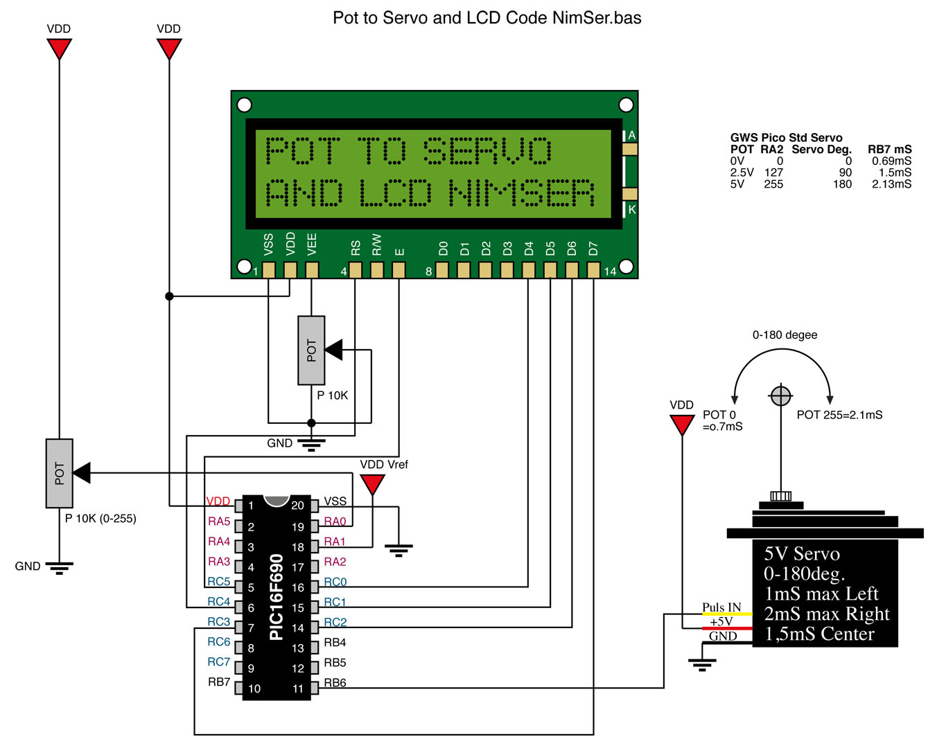
Actually i have this code for display the value on a LCD. Now i want the value of 0 to be 1mS puls and 255 to be 2mS puls.
Se attached drawing.
Hope this helpCode:' Name : ServoTester.pbp ' Compiler : PICBASIC PRO Compiler 2.6 ' Assembler : PM or MPASM ' Target PIC : PIC16F690 or similar type compatible with LAB-X20 board ' Hardware : LAB-X20 Experimenter Board ' Oscillator : 4MHz external crystal ' Keywords : ADCIN, LCDOUT ' Description : PICBASIC PRO program to read pot and display on LCD. ' FUNKAR ROR EJ ' Define LCD pins Define LCD_DREG PORTC 'LCD data port Define LCD_DBIT 0 'LCD data starting bit 0 or 4 Define LCD_RSREG PORTC 'LCD register select port Define LCD_RSBIT 4 'LCD register select bit Define LCD_EREG PORTC 'LCD enable port Define LCD_EBIT 5 'LCD enable bit ' Allocate variables x Var Byte ANSEL = %00000100 ' Set PORTA.2 analog, rest digital ANSELH = %00000000 Pause 100 ' Wait for LCD to start mainloop: Adcin 2, x ' Read ADC value on AN2 (PORTA.2) Lcdout $fe, 1, "Pot1 = ", #x ' Send value to LCD Pause 50 ' Do it about 10 times a second Goto mainloop ' Do it forever End[/I][/I]
Thronborg
Servo Tester.pdf
Last edited by ScaleRobotics; - 12th March 2011 at 16:53.
Ken, take a look at this Electronics with Micro-controllers
Why pay for overpriced toys when you can have
professional grade tools for FREE!!!
Thank's, now i start to understand a little bit more. Its running fine but i got the feeling that i had to much code.
Actually i dont know why i had the ANSEL, ANSELH and ADCON, it seems to work without them. Any ideas?
'************************************************* ***************
'* Name : NimSer.BAS *
'* Date : 3/3/2011 *
'* Notes : Move Servo 1 to 2mS depend on POT value *
'* Show valu in mS on LCD display *
'* For standard servo settings 1-2mS set LOW_servo con 100 *
'* and HIGH_servo CON 200 *
'************************************************* ***************
'Define OSC and ADC
DEFINE OSC 4 ' Set internal Oschillator to 4Mhz
DEFINE ADC_BITS 8 ' Set number of bits in result
DEFINE ADC_CLOCK 2 ' Set clock source (3=rc)
DEFINE ADC_SAMPLEUS 50 ' Set sampling time in uS
' Define LCD pins
Define LCD_DREG PORTC 'LCD data port
Define LCD_DBIT 0 'LCD data starting bit 0 or 4
Define LCD_RSREG PORTC 'LCD register select port
Define LCD_RSBIT 4 'LCD register select bit
Define LCD_EREG PORTC 'LCD enable port
Define LCD_EBIT 5 'LCD enable bit
TRISA = %00001001 ' RA0 = A/D input
ADCON1.7 = 0 ' RA.1 = +Vref, Set PORTA analog and left justify result
PORTb.6 =0 ' Prepare RB0 for high-going pulseout
ANSEL = %00000100 ' Set PORTA.2 analog, rest digital
ANSELH = %00000000
' Variables
outpuls VAR WORD ' Variable for the calculated puls out in mS
POT_POS VAR BYTE ' Pot position CC=0, CCW=255
LOW_servo con 60 ' Min Servo pulse 60= 0.6mS 100=1mS
HIGH_servo CON 200 ' Max Span from LOW_servo to HIGH_servo
' Span 100 gives 100+100 = 200=2mS
Pause 500 ' Wait for LCD to start
MainLoop: ' The Loop start here!
ADCIN 0,POT_POS ' Read A/D channel 0 to variable SVO_POS
outpuls =LOW_servo + (POT_POS *HIGH_servo/255) 'Calculate the outpuls in mS
Lcdout $fe, 1, "POT_POS= ", #POT_POS ' Display POT Valu between 0-255 on line 1
LCDOut $fe,$C0, "Puls= ",DEC (outpuls/100),".", DEC2 outpuls,"mS"' Display pulswith in mS on line 2
PULSOUT portb.6 ,outpuls ' Move servo on pin
PAUSE 20 ' Constant 20mS pulses(low) between outpuls
GOTO MainLoop ' Forever
End
Last edited by thronborg; - 15th March 2011 at 02:02.
Hello, I am back with a robocar - PBP question. I wish I had the will power to really study this.
My robocars use HPWM to control the steering and to drive the Electronic Speed Control => DC motor for the wheels. I am trying to calibrate this command given different little cars.
Before the "main:" label I placed some code to make the wheels turn and steer. I discovered that HPWM rides through the PAUSE command sometimes and not other times. It depends on what code precedes the HPWM commands. Immediately below is a case that works. Below that is a case that does not. By not work, I mean the wheels just do not move.The only difference is the presence of the WHILE loop at the beginning.
The WHILE loop at the front checks the power status of the radio transmitter. If channel3 (PORTC.4) is pulsing the radio is receiving a signal from its transmitter. This works. It gives me an opportunity to put the car down on the floor.
What'z up here with HPWM and PAUSE???
-----THIS WORKS: Turn OFF the transmitter and the wheels move---------------
switchtoPIC = 2
WHILE switchtoPIC >= 2
COUNT channel3,65,switchtoPIC
HIGH portc.0
WEND
HPWM 1, Left, 50
HPWM 2, Forward, 50
pause 1000
HPWM 1, HalfLeft, 50
HPWM 2, HalfForward, 50
pause 1000
HPWM 1, Straight, 50
HPWM 2, brake, 50
pause 1000
main:
------THIS DOES NOT WORK. THE WHEELS DO NOT MOVE until main: ----------
HPWM 1, Left, 50
HPWM 2, Forward, 50
pause 1000
HPWM 1, HalfLeft, 50
HPWM 2, HalfForward, 50
pause 1000
HPWM 1, Straight, 50
HPWM 2, brake, 50
pause 1000
main:
Would it help if I were to show you the assembly language code for the above two compilations?
Ken
I need help gang. This is definitely a PBP issue. Do you all have any idea where I should start?
Ken
Hi Ken,
HPWM is hardware based, so it keeps going while other things happen.
Check out the manual:
It can run continuously in the backgroundwhile the program is executing other instructions.
You might try trouble shooting your output signal, to see what is happening.
HPWM is a hardware command. It runs while PAUSE is pausing except (it appears) when it is the first "active" command in the code. Really. Truly. The only difference between those two snippets of code is the WHILE statement at the beginning of the one that works.
Note: These few lines of code precede the 'main:' label. All I am trying to do is to demonstrate that the wheel controls are working before experimenting with racing. Once the program counter gets past 'main:' both versions run identically.
Ken
Yes, but how are you checking to see that hpwm is not working, sometimes. Are you really observing the signal itself, or just the reaction it is "supposed" to cause? You have the tools to look at the source .... why not use them?
I compile the code with the WHILE command. During the first three seconds after powering up the wheels steer and roll as expected. I then comment out the WHILE, recompile and program. For the first three seconds the car does nothing. The PAUSEs work but the HWPM commands do not.
After the initial three seconds both programs work identically.
Ken
You really need to test the signal Ken. Without observing the signals, you really can't say HPWM doesn't work. How about getting your Pickit2 out and using the logic probe again?
Scalerobotics:
I used the oscilloscope you gave me way back when. You are correct. The PWM signals appear to be there from the get go, but the wheels neither rotated nor steered until the program counter got past 'main:'.
The pulse traces on the scope are stable and easily readable.
All my fault - nothing new there - just between us programmers. I thought I had set PORTC.0 low with a TRISC = %11110000 when in fact I had set it to be an output. This is the pin that drives the DPDT switch that selects between PIC control and radio receiver control. Once I activated the LOW portc.0 located just before the HPWM commands. Lo and behold!
Thank you for your patience and smarts.
Ken
One of you knowledgeable people please come to my aid.
I am studying the .ASM code which my PBP produces. My Microchip 16F887 Data Document DS41291F page 232 lists the Assembly Language commands for the 16F88x chips. There is no HPWM in that list. Yet my .asm code contains:
HPWM?CCC 001h, _Right, 032h
How does the Assembler know what to do with that string?
I figured it must be in one of the includes. I searched all the files in the PBP directory, the Mecanique directory and the Microchip directory for the string HPWM. No luck except in my .pbp code that I wrote and its resulting .asm.
This is not a show stopper, but I would like to know what I am missing.
On the very good news side, MIT's Lincoln Laboratory has an Educational Outreach initiative. They have picked up the idea of racing robocars. I am sure that they will take this to the next level - whatever that is.
Ken
In the PBP directory there is a file , pbppi14e.lib , that has the macros.HPWM?CCC 001h, _Right, 032h
How does the Assembler know what to do with that string?
Dave
Always wear safety glasses while programming.
Thank you Mr/Ms Mackrackit
pdppi14e.lib catches all my questions (for example how does PAUSE work) except one. HPWM is nowhere to be found. I know it is a hardware feature (whatever that means). Somehow the assembler has to know how to translate it into .hex.
All in all, as I said, my robocar project is progressing. Anybody got any ideas what other kind of do it yourself robots might hook middle school students?
Ken
It's in there ... about 1/4 the way through.
Code:;**************************************************************** ;* HPWM : Output a pulse width modulated wave in hardware * ;* * ;* Input : W = channel 1 - 5 * ;* : R1 = frequency * ;* : R4 = duty cycle * ;* Output : None * ;* * ;* Notes : * ;****************************************************************
I must have spelled HPWM wrong.
 Members who have read this thread : 4
You do not have permission to view the list of names.
 Posting Permissions


Bookmarks