adequate pull-down resistor value


Closed Thread
Results 1 to 10 of 10
  1. #1
    Join Date
    Feb 2009
    Posts
    6

    Default adequate pull-down resistor value

    Hi there guys Im new here... Im from Brazil so Im sorry if you guys cant understand my poor english :P

    I did some guessing job when finding the components value in this circuit, and I was already expectating some issues.. but Im really noob with electronics and I cant find a way for solving this. Heres my circuit in PDF format:


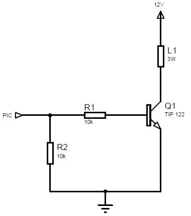
    Its very simple.. you can see 8 lamps that will blink in a frequency given by the PIC. My big problem is when they are NOT blinking... When I turn of my circuit using that switch but keep it connected to the power source (an ATX PC power source) some of the lamps blinks weakly from time to time... its really annoying :P So I realised that transistors were receiving so much ESD for being darlington ones, that made me add that resistor (R12) wich one should grant 0V at the transistors bases..

    Sadly there still one lamp that keep blinking..
    My question is: How to find the resistor value that I shall use on R12?!! I think that a bigger value would make all the lamps to light again when source turned off, cause there will be no more "grounding" enough to "ground" the transistor base. And I think a lower value would reduce the lamps lighting when source turned off, cause there will be a easier way for the current flow... So whats the corret value?!?!


    Its a shame cause its a very simple circuit.. Can you guys please help me solving it??

    Plz! Thank you.


    *EDIT: Guys, I noticed that my circuit generates some ESD that my television can feel... how can I solve it? I think those ISO especifications will be my next class topic... but can you guys teach me anything about preventing from being a source or a victim of ESD?! Thanks again!
    Last edited by r0nd0m; - 6th February 2009 at 23:30. Reason: forgot to mension this

  2. #2
    Join Date
    Feb 2009
    Posts
    6


    Did you find this post helpful? Yes | No

    Default

    Ok I think you guys wont help me if I ask like this, sorry, so let me rephrase:

    In this section of circuit I need to find the correct value for this resistor, can you guys tell me if am I right:


    So, from the PIC I got 5V when that pin is logically high. I know pic sources at maximum 20/25mA, thats why I got the R1 wich makes arrive just 0,5mA at the TIP122 and thats suficient for connecting my big led of 3W and the ground (cause the gain is 1000).

    The led is 3W so when at 12V passes through him 250mA. And thats exactly what I got. According to the datasheet its collector nominal current is 5A (and all Leds current summed is just 2A, so it could hold the whole circuit by himself, wich is pretty good :P but its not gonna happen).

    Now my big trouble: When I added that seccond resistor trying to send all that EMI to the ground (what worked pretty well), the current sent by the PIC isnt the same anymore. So if this 2nd resistor is also 10K PIC should send him 0,5mA too, so he would send 0,5+0,5 = 1mA is that right???

    Theres anything else that shall I worry about? Plz help!
    If thats all and correct I finally understood how to find a pull down resistor :P

    Thanks!

  3. #3
    Join Date
    Feb 2009
    Posts
    4


    Did you find this post helpful? Yes | No

    Default

    Call me crazy, but why not replace pulldown resistor R2 with a small trimpot and simply adjust it until the unwanted behavior disappears?

  4. #4
    Join Date
    Sep 2004
    Location
    montreal, canada
    Posts
    6,898


    Did you find this post helpful? Yes | No

    Default

    Clarify that "...all that EMI to the ground..." sentence.... which EMI, Where?

    Your base resistor is a tad high (well... for a purist)

    Are you aware of TIP122 internal resistors?

    R2 shouldn't be needed
    Steve

    It's not a bug, it's a random feature.
    There's no problem, only learning opportunities.

  5. #5
    Join Date
    Feb 2009
    Posts
    6


    Did you find this post helpful? Yes | No

    Default

    Ehm guys... thank you but I kinda.. solved the problem.

    Thank you anyway.
    Cya soon.

  6. #6
    Join Date
    Sep 2004
    Location
    montreal, canada
    Posts
    6,898


    Did you find this post helpful? Yes | No

    Default


    Thanks for posting your solution here with as this much details, all forum member and reader will learn a lot from it
    Attached Images Attached Images  
    Steve

    It's not a bug, it's a random feature.
    There's no problem, only learning opportunities.

  7. #7
    Join Date
    Aug 2006
    Location
    Omaha, Nebraska USA
    Posts
    263


    Did you find this post helpful? Yes | No

    Default

    Did you try a capacitor instead of R2?

    And how did you solve the problem? Inquiring minds want to know . . .
    Last edited by RussMartin; - 10th February 2009 at 00:43.
    Russ
    N0EVC, xWB6ONT, xWN6ONT

    "Easy to use" is easy to say.

  8. #8
    Join Date
    Feb 2009
    Posts
    6


    Did you find this post helpful? Yes | No

    Default

    Quote Originally Posted by mister_e View Post
    Clarify that "...all that EMI to the ground..." sentence.... which EMI, Where?
    I think I have told you that already in the first post. When I connected the osciloscope on the led I found so much "noise" in the wave form. The circuit is suposed to generate some frequencies that will blink the 3W leds... So if you look at one led with the osciloscope, you will see a square waveform, of maximum amplitude of 5V and minimum amplitude of 0V. Due to the noise (the EMI/RFI not ESD sorry for that) the wave form gets messed, mainly during the 0V period of the waveform.. the noise creates some pikes on the 0V periode wich ones gets close to the 5V... enough to activate the TIP122 cause its gain is really high (10000). So even with the circuit completly turned off, that noise makes the leds to blink.

    Quote Originally Posted by mister_e View Post
    Your base resistor is a tad high (well... for a purist)
    Yes I know.. you will crucify me but I didnt take much care of it..

    Quote Originally Posted by mister_e View Post
    Are you aware of TIP122 internal resistors?
    Yes I heard about that... as it seems, they arent sufficient for preventig that damn noise..

    Quote Originally Posted by mister_e View Post
    R2 shouldn't be needed
    Yes I think the same but that thing is the only thing that solved my problem..
    It sends to the ground all the EMI/RFI issues that circuit may suffer.. As far as I know..

    Quote Originally Posted by RussMartin
    Did you try a capacitor instead of R2?
    I was afraid of using a capacitor cause it could drawn my frequency, so I chose the resistor to send it to dust!


    Quote Originally Posted by mister_e
    Thanks for posting your solution here with as this much details, all forum member and reader will learn a lot from it
    Im sorry for taking that long time for answering, I dont wanna be selfish mr e, I just cant explain better it takes me a really long time to translate.. -> bad english, remember that!

    Ty guys, hope this thing can be useful.
    Cya soon!
    Last edited by r0nd0m; - 10th February 2009 at 19:57.

  9. #9
    Join Date
    Sep 2004
    Location
    montreal, canada
    Posts
    6,898


    Did you find this post helpful? Yes | No

    Default

    Don't take my comment as an offense. To be honest, I would like to apologize for that. It was one of those bad days... sorry

    Don't worry about your English... I really do understand what you mean and how you feel... I'm French... but Canadian/Quebecer ( va chier Alain )
    Steve

    It's not a bug, it's a random feature.
    There's no problem, only learning opportunities.

  10. #10
    Join Date
    Feb 2009
    Posts
    6


    Did you find this post helpful? Yes | No

    Default

    lol, thats ok mate

    Cya soon guys!

Similar Threads

  1. Pull Up enabled and PWM question
    By financecatalyst in forum mel PIC BASIC Pro
    Replies: 5
    Last Post: - 7th September 2009, 08:21
  2. Weak pull Up 12F629
    By Lionheart in forum General
    Replies: 1
    Last Post: - 9th December 2008, 21:07
  3. 12F683 internal pull up
    By hvacrtech in forum mel PIC BASIC Pro
    Replies: 7
    Last Post: - 27th July 2008, 02:35
  4. accessing EEPROM with pull down switches
    By earltyso in forum mel PIC BASIC Pro
    Replies: 0
    Last Post: - 22nd October 2007, 20:40

Members who have read this thread : 1

You do not have permission to view the list of names.

Posting Permissions

  • You may not post new threads
  • You may not post replies
  • You may not post attachments
  • You may not edit your posts